Scan tools have come a long way in the past decade, such that improvements in sample rates and display capabilities can give technicians vital insights into multiple areas under a vehicle like wheel speed sensors, ride height sensors and oxygen sensors.
A modern scan tool can graph the output of multiple data PIDs on a test drive, which is how the control module sees and interprets the data. For example, if you see sudden drops in speed from a wheel speed sensor, it is a sign that the air gap between the encoder ring and sensor has changed due to “play” inside the bearing. This can point you in the right diagnostic direction and help you focus on one corner or system of the vehicle.
On most late-model vehicles, the ABS, ECU and electric power steering communicate using a high-speed controller area network (CAN) bus. Often, problems are related to communication errors, which could be inside a module or the wiring connecting the modules.
Using a scan tool to communicate with the different modules can confirm operation and the source of communication codes. It can even reveal where the problem with a network’s wiring is located. The scope can then be used to verify the condition of the network.
Scoping Circuits and Sensors
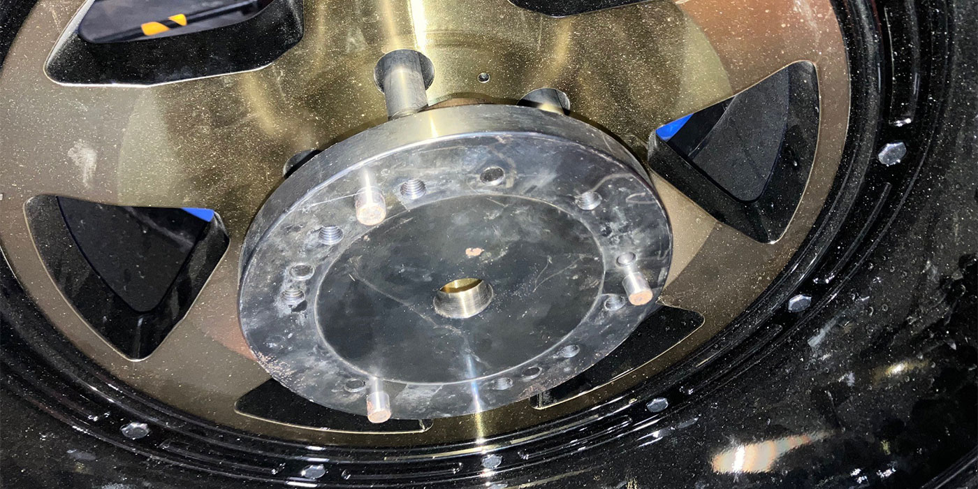
An oscilloscope or scope can measure more than just the output of the signal. Testing with a scope can reveal the health of the circuit and if it is active. For example, an active wheel speed sensor receives voltage from the ABS module (ranging from 8 to 12 volts) and changes the voltage signal by only 0.6 to 1.2 volts. The square wave’s peaks and valleys show the alternating polarity magnets in the encoder ring passing by the tip of the sensor. With a captured waveform, you can see the circuit’s health by the voltages matching a “known good” waveform. You can also see mechanical problems like a damaged reluctor ring or misaligned airgap.
Bias Voltage Checks
Almost every sensor for the brakes, suspension and even oxygen sensor heaters do a bias voltage self-diagnostic check when a module awakens. To protect itself, a module sends out a low-voltage signal for a millisecond when it is first turned on. Modules do this because there is no fuse between the sensor and the circuit board. You can see this signal better on a scope rather than a meter with a min/max function.
If the circuit is compromised by an open or short, the increased or decreased resistance will cause the voltage to drop or exceed specifications. If the readings from the bias voltage tests are correct, the module provides voltage to the circuit for operation. If the readings are not in the predicted range, the module will not supply power and will set a code and deactivate the systems. Bias voltage tests also work to detect opens in the circuit. This is why if a sensor is disconnected, it will cut power and set a code. When the untrained technician does not see power at the sensor, he may think the module is defective and replace the module. To read the voltage with the system on, you will have to back-probe a connector or use a bypass harness to test the circuit.