Oxygensensors have been a part of the automotive maintenance scene since 1976, whenfeedback fuel controls were popularly introduced. By 1980, nearly every car andlight truck was equipped with an oxygen sensor that allowed theircomputer-controlled fuel systems to operate in a “closed-loop,” “feedback” or“fuel control” mode. 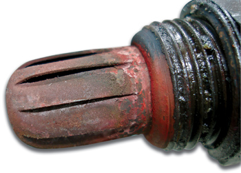
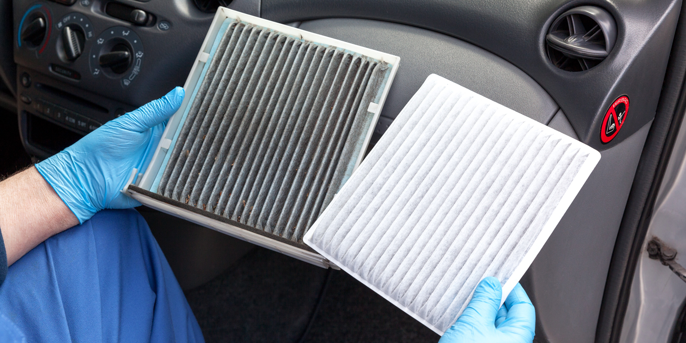
Earlysingle-wire zirconia oxygen sensors are usually replaced at 30,000-50,000-mileintervals or should be tested when a “maintenance” warning light isilluminated. Back in the day, early oxygen sensors often failed due totetra-ethyl lead and silicon (dirt) contamination. Early oxygen sensors alsobecame contaminated with phosphorous contained in engine oil, glycol containedin engine coolant and vapors emanating from silicone gasket sealants. SeePhoto 1.
Modernzirconia and air/fuel ratio (AFR) oxygen sensors last much longer because mostof the above contaminants have been removed from gasoline, engine oil andgasket sealants. Since vehicles are being driven much longer, zirconia and AFRsensors most often malfunction because their internal heater circuits fail orbecause their zirconia-based sensing elements eventually lose their sensitivityto rapid changes in the engine’s air/fuel ratio.
OxygenSensor Terminology
Oxygen sensor diagnosis requires an intimate knowledge of oxygen sensorterminology. The earliest version of the oxygen sensor was originally called a“lambda sensor,” because it could detect when an air/fuel mixture varies froman ideal 14.7:1 weight ratio. Ideally, 14.7 parts of air mixed with 1.0 partsof fuel will completely oxidize, leaving only water and carbon dioxide. Theterm “stoichiometric” describes the state in which chemically perfectcombustion is achieved. 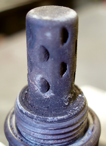
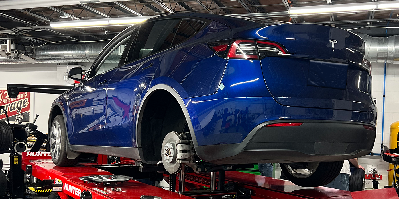
Incontrast to stoichiometric, Lambda indicates when the actual air/fuel mixturevaries from the chemically perfect 14.7:1 a/f ratio. Lambda 1 indicates aperfect 14.7:1 a/f ratio, while a Lambda number of less than 1 indicatesinsufficient air supply. A Lambda number that’s greater than 1 indicatesinsufficient fuel in the cylinder. See Photo 2.
HeatedOxygen Sensors
During the early 1980s, many engines didn’t achieve fuel control (open-loop)until the coolant warmed to 160° F and the oxygen sensor warmed to 600° F.Since most exhaust pollution occurs during and shortly after a cold enginestartup, oxygen sensors were later equipped with electric heaters to quicklybring them up to operating temperature. In modern vehicles, the PCM enters fuelcontrol (closed-loop) as soon as the oxygen sensor begins sending a readablevoltage signal to the PCM. Although operating strategies vary according toapplication, the PCM generally activates the oxygen sensor’s heater circuitduring cold startups. Heated oxygen sensors generally last between60,000-100,000 miles.
TheZirconia Oxygen Sensor
The sensing element of most oxygen sensors is composed of a zirconium dioxidethimble coated on both sides with a thin layer of platinum. As mentioned above,zirconia sensors must reach 600° F operating temperature before they begingenerating a voltage signal. In addition, the inside of the zirconia thimblemust be exposed to oxygen, which reaches the thimble through a vented housingor through the sensor lead wire. Although very little oxygen is required, acoating of engine oil or grease can reduce the availability of oxygen to theinner thimble enough to affect the sensor’s accuracy. 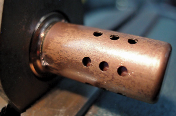
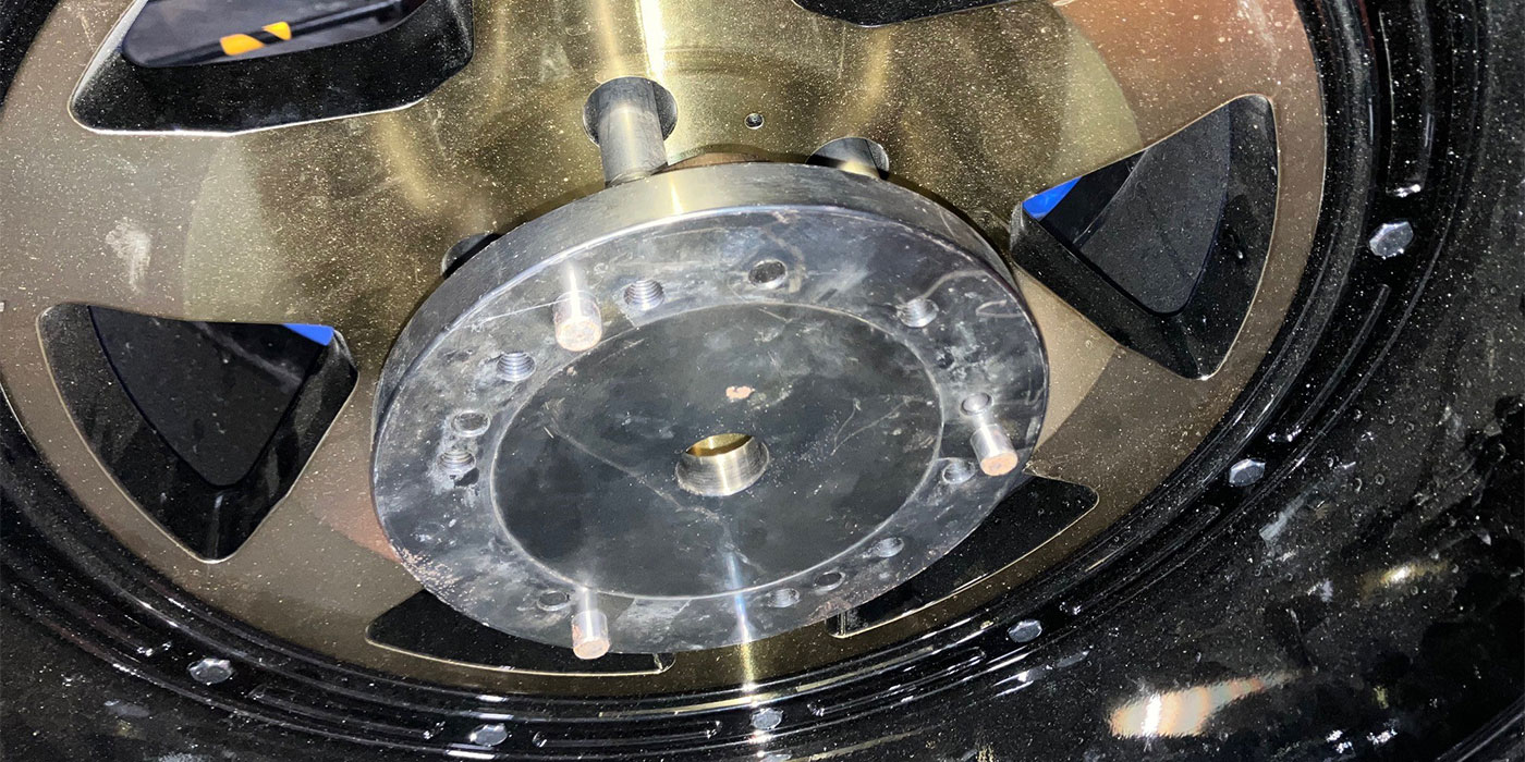
Whenthe actual a/f mixture is rich, the sensor generates a 0.8 to 0.9-volt signalto the PCM. When the actual a/f signal is lean, the sensor generates amuch lower voltage signal to the PCM. At stoichiometric or Lambda 1, the sensorgenerates about 0.450 volts. When the oxygen sensor indicates “rich,” the PCMreduces the fuel injector pulse width. When the O2 sensor indicates “lean,” thePCM increases the injector pulse width. See Photo 3.
But,in reality, the combustion process is seldom perfect because the fuel closestto the combustion chamber surface or between the piston and cylinder wall oftendoesn’t burn. Consequently, a small amount of partially burned fuel in the formof carbon monoxide and unburned fuel in the form of hydrocarbons remains toform pollutants in the exhaust gas stream.
Tomore accurately monitor fuel control, the PCM in modern systems switches theair/fuel ratio from about 0.2 volts to 0.8 volts, which is very close tostoichiometric. This switching process can easily be observed by using thevoltage-graphing feature found on most scan tools. In contrast to using alabscope, the graphing sample rate might be too low on a scan tool to provideabsolutely accurate information. Nevertheless, the scan tool graph willindicate the voltage switching range and relative activity of the zirconiasensor.
Whendiagnosing any oxygen sensor, remember that outside air entering the exhaustsystem from an exhaust leak will obviously reduce an oxygen sensor’s indicatedvoltage output. It’s also important to know that oxygen sensors can become richor lean biased due to problems like sensor contamination and faulty sensorgrounds. Remember that, regardless of how well it tests, a biased sensor willnot produce a stoichiometric air/fuel ratio. So, if the sensor is questionable,it should be replaced. 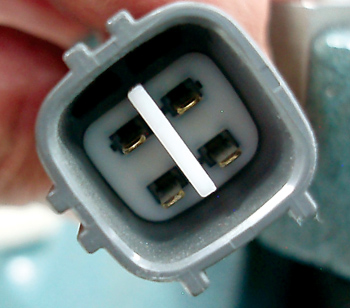
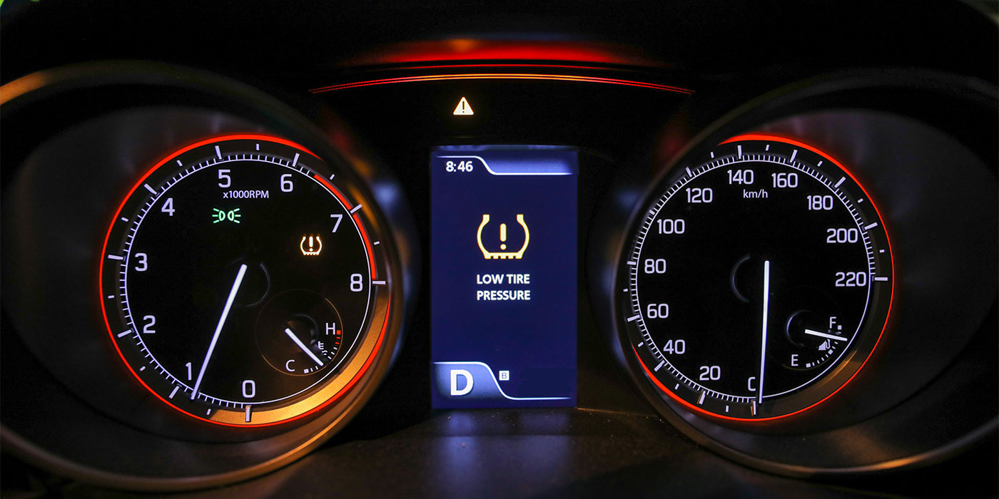
Inmany post-1996 OBD II systems, the zirconia sensor has changed from athimble-shaped configuration to what is known as a “planar” or flatconfiguration. The planar design allows a much shorter warm-up time, is morereliable and is more accurate over its operating life. On most currentplatforms, zirconia sensors are used downstream from the catalytic converterbecause the voltage reporting requirements are within the range of a zirconiasensor. See Photo 4.
TitaniaOxygen Sensors
Just for the historical record, some manufacturers like Toyota usedtitania-based oxygen sensors to indicate rich or lean air/fuel mixtures. Unlikea zirconia sensor that produces voltage, the titania-based sensor is generallysupplied with 5.0 reference volts. As a titania-based sensor heats up, itresponds to variations from stoichiometric by changing resistance. Although theapplications for titania-based sensors are relatively few, a technician mustbe able to recognize this configuration when a diagnosis is required.
Air/FuelRation Sensors
AFR sensors are used in engines operating at extreme air/fuel ratios from 12:1to 20:1 or higher. While AFR sensors are also known as “linear,” “broad-band,”“wide-band” and “lean” air/fuel ratio sensors, each of these design variationsis generally application-specific and can generate a slightly different datastream.
Althoughan AFR sensor is basically two zirconia sensors or “cells” mated together inplanar form, the AFR sensor uses an entirely different operating strategy thana conventional zirconia sensor. To remain within the scope of this article,suffice it to say that one cell is used to measure oxygen content in theexhaust stream and the other cell, known as a pumping cell, is supplied with avery small electric current capable of moving oxygen ions in a positive ornegative direction. In so doing, this electric current achieves astoichiometric ratio between both cells. The PCM therefore controls air/fuelratio by measuring the amount of electric current flowing to and from the AFRsensor.
Thedifferences between a conventional zirconia and AFR sensor are, first, that theAFR sensor will have five or more wires in its connector. Second, the AFRsensor must operate at 1,200° F, so it’s generally dependent upon its heatercircuits to maintain operating temperature. And, in contrast to zirconia sensordiagnostics, AFR sensor diagnostics are, for practical purposes, scan-toolbased.
Ifyou’re using a factory or “enhanced” scan tool, you’re likely to see AFR datadisplayed in an entirely different format than on an aftermarket tool. Manyaftermarket scan tools were mandated to display AFR data in a conventional 0 to1-volt switching pattern format.
Whilethis format is erroneous in one sense, it also becomes irrelevant in anotherbecause modern OBD II PCMs have a much greater and far more sophisticatedon-board diagnostic capability than just a few years ago. So, in most cases,it’s much better to let the modern OBD II PCM run the diagnostic monitors onthe AFR sensor and store the related trouble codes when the AFR sensor beginsto degrade.
BecauseAFR sensors can detect a wide range of air/fuel ratios in the feed gasesexiting the engine, they are generally used upstream of the catalyticconverter. Again, remember that leaking exhaust manifolds or EGR systems willcreate a false AFR signal to the PCM.
OxygenSensor Identification
Scan tools identify oxygen sensors according to cylinder bank and position.Number-one cylinder bank is the bank closest to the harmonic balancer on aV-block engine. In relation to the catalytic converter, the B1S1 oxygen sensoris the first or “upstream” oxygen sensor on the bank one side. B1S2 is thesecond sensor located downstream from the catalytic converter. Some systems usetwo upstream bank sensors per cylinder bank and are numbered accordingly.
Whento Sell Oxygen Sensors
Although it’s obvious that a new oxygen sensor is required when the PCM detectsa failure, there are other occasions when an oxygen sensor replacement might berecommended. As mentioned at the outset, many older import vehicles areequipped with sensors that should be replaced at regular intervals or inspectedwhen the vehicle’s orange “maintenance required” light illuminates.
Becausepre-1996 OBD I vehicles lack the on-board diagnostic capability to detect afailing zirconia oxygen sensor, it’s always best to test sensor voltage rangeand sensitivity with a labscope or digital multimeter. When removed, the sensorshield should exhibit a nearly clean-metal appearance. If the sensor iscrusted with oil contamination, it should be replaced and the engine testedfor excessive fluid consumption.
Similarly,if an oxygen sensor has been exposed to coolant from a leaking cylinder headgasket, it should be replaced to ensure the PCM’s ability to establish correctfuel control.
Last,if the vehicle is failing an emissions test, remember that sensors can producea biased voltage due to internal or external contamination, or a faulty groundconnection. In any case, a questionable sensor should be replaced to ensureaccurate fuel control.