 When many of us started our careers in the wheel alignment trade, we inevitably experienced a vehicle that would come back with steering quality complaints or unevenly worn tires after having had the caster, camber and toe angle adjusted to specification. Tire casing problems aside, the fault would nearly always be found in defective steering geometry caused by a bent steering knuckle assembly.
Bent steering knuckle assemblies are easy to ignore simply because they do require extra time and effort to measure and evaluate in today’s fast-paced undercar service market. Nevertheless, the symptoms of bent steering knuckles are easy to spot, especially if we do a thorough pre-alignment inspection.
Caster, Camber and Toe
Let’s begin with a recap of caster, camber and toe angles. Positive caster angle is best illustrated by the rearward tilt of the steering fork on a bicycle. Positive caster obviously places the front wheel ahead of its pivot point and most vehicles are designed with positive caster angle.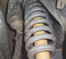
In contrast, negative caster angle is best illustrated by the casters on your toolbox trailing their pivot points. When weight is applied to the two front wheels of a vehicle, positive or negative caster forces the front wheels to a centered position. Caster angle, therefore, helps reduce steering wander or the need to constantly steer the vehicle.
Camber is the vertical position of the wheels in relation to the road surface. Negative camber results when the tops of the two front wheels tilt inward toward the chassis centerline. Positive camber results when the tops of the wheels tilt outward from the chassis centerline. Positive camber works in conjunction with king pin or steering axis inclination (SAI) to reduce steering effort. On older vehicles with individually replaceable wheel bearings, positive camber places the vehicle weight squarely on the larger inner wheel bearing.
Toe is the most critical tire-wearing angle. Wheels pointed inward from the centerline are “toed” in, wheels pointed outward from centerline are “toed” out. A slight amount of toe-in is required to prevent the front wheels from following ruts or contours in the road. Slight amounts of toe-in also compensate for flexing and wear in the tie rods and tie rod ends, as well as for minor changes in suspension height and geometry.
SAI and Steering Radius
Two steering geometry angles, SAI and steering radius, are built into the steering knuckle and are, therefore, non-adjustable. In the real world, defects in SAI and steering radius often go unnoticed if the vehicle is driven primarily on four-lane, interstate-style highways. On the other hand, if the vehicle is primarily driven through many turns on city streets, defects in SAI and steering radius might show up immediately.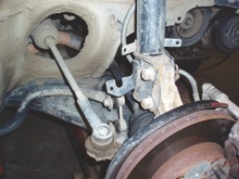
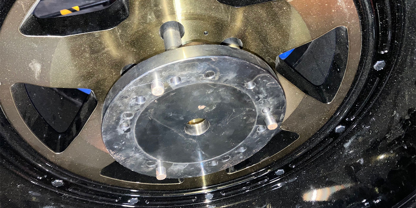
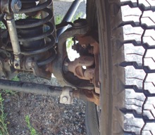
The upper ball joint or strut support bearing on a front suspension is closer to the chassis centerline than the lower ball joint. An imaginary line drawn through the upper strut support bearing or ball joint and lower ball joint should theoretically intersect with the centerline of the tire at the point of road contact. See Photo 1.
SAI consequently allows the wheel to pivot on its centerline. If the SAI is incorrect, the tires begin to swing in a radius around this theoretical pivot point. Incorrect SAI caused by bent struts, bent spindles or excessively offset wheels will result in greater steering effort and accelerated suspension system wear. See Photo 2.
SAI also tends to return the front wheels to center because, when combined with caster angle, SAI tends to apply more weight on the inside front wheel by lifting the chassis an inch or two. At center, SAI acts in combination with the caster angle to reach equilibrium on both wheels. Again, SAI combines with caster angle to reduce steering wander.
Last, SAI and caster angle generally increase the positive camber angle of the inside tire and decreases positive camber angle of the outside tire during a turn. This camber change counteracts the tendency of the tire tread to lift from the road surface during a turn.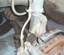
Steering Radius
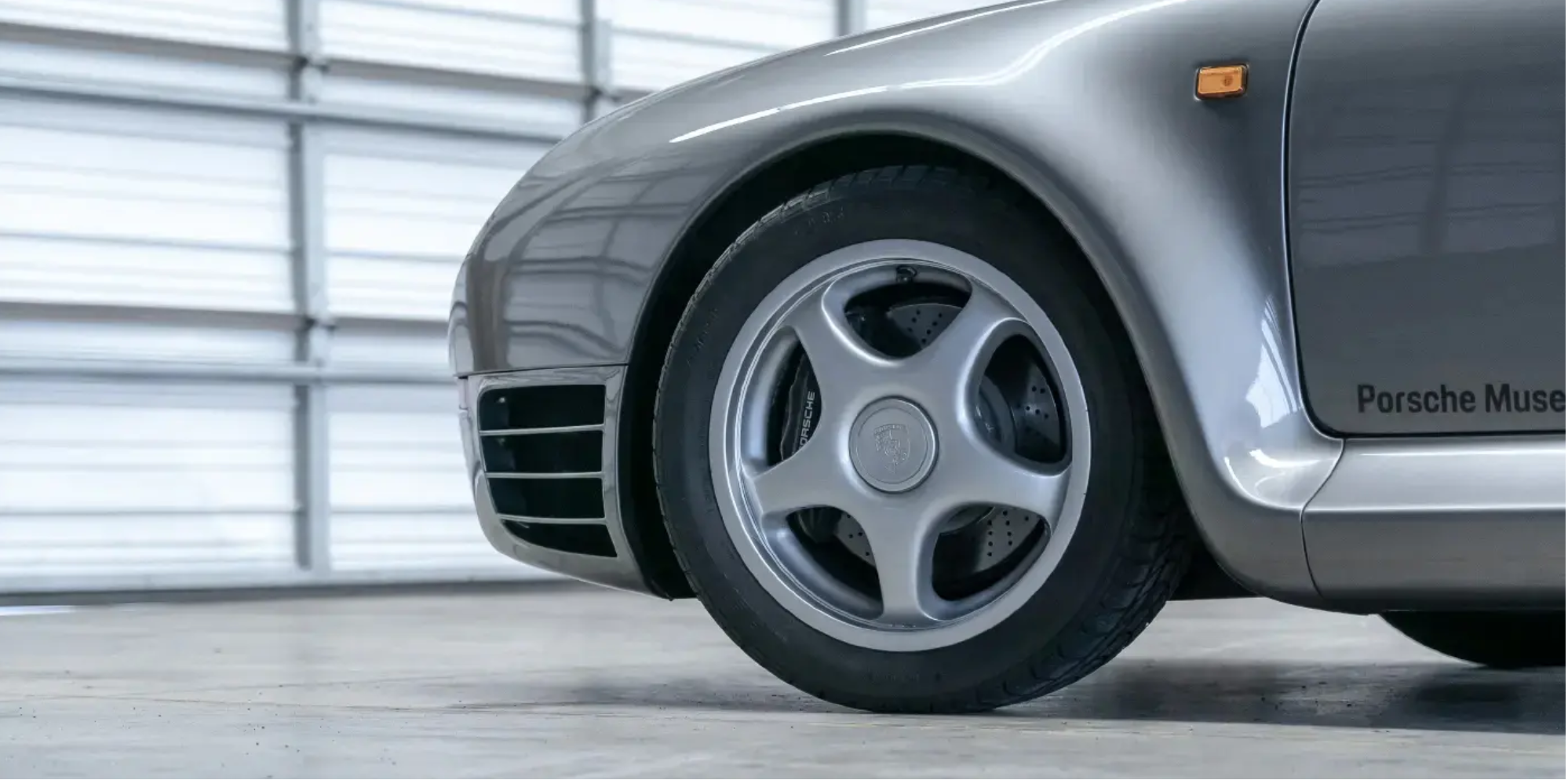
Because the inside wheel turns through a shorter radius than the outside wheel, the steering system must change from toe-in to toe-out to reduce tire scrub when navigating a sharp corner. The portion of steering knuckle responsible for turning the inner wheel through a sharper turning radius is the steering arm, which connects the tie rod end to the steering knuckle. See Photos 3 and 4.
The angle of the steering arm intersects the vehicle centerline at approximately the length of the vehicle’s wheelbase. The angle of the steering arms allows the rear wheels to track more closely with the front when turning a corner.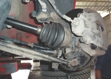
The actual process of going from toe-in (or toe zero) to toe-out when navigating a turn is known as the Ackerman Effect, which causes the inner front wheel to toe out about two degrees more than the outer front wheel on a 20-degree turning radius. See Photo 5.
The Ackerman Effect, like most alignment angles, is always a compromise between different driving conditions. A NASCAR Toyota, for example, might have very little Ackerman angle because the car is driven through long, sweeping curves, often at a slight drift angle. In this case, two degrees of Ackerman would increase tire wear and negatively affect the driver’s control of the vehicle. Most NASCAR vehicles feature a slotted steering arm that allows Ackerman angle to be adjusted on each steering arm to meet track conditions.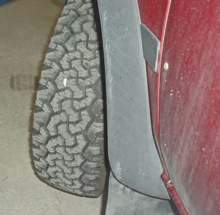
At the other extreme, a metro-area delivery van steering around 90-degree street corners and into very confined turn-around areas would need at least two degrees differential in Ackerman angle to make precise turns and reduce front tire wear. If our prototype delivery van didn’t have a sufficient Ackerman angle, the vehicle would tend to “push” going around a sharp corner, which would result in poor steering response and accelerated tire wear.
Tire Issues
While space doesn’t allow a complete discussion of tire wear diagnostics, keep in mind that the old bias-ply designs of the ’60s produced very high rolling friction and were very sensitive to incorrect camber and toe angles. The bias-ply belted tires of the 1970s and ’80s were improved designs, but often produced inner rib wear and other tire wear anomalies when mated with steering geometries designed for bias-ply tires. Current passenger tire designs generally use a very flexible sidewall and firm tread belt. Flexible sidewalls tend to make the tire less sensitive to the negative camber and high caster angles used in modern steering geometries.
Negative camber angles are used in modern steering geometry because they greatly increase the tread contact pattern at high cornering speeds. Increased caster angle complements this effect and, thus, improves steering quality and response. Because modern suspension systems are more stable and produce much less toe variation in response to changes in suspension height, toe angles themselves have been reduced in most cases.
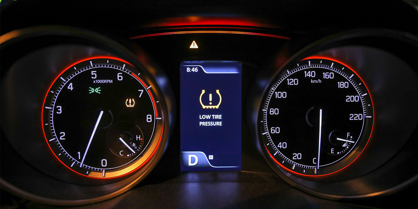
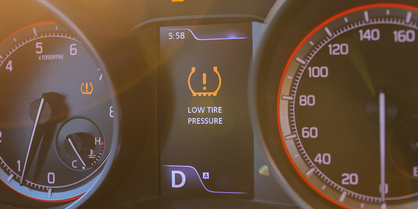
Always inspect tire pressure before road testing, as well as the tires for matching casing design, size and tread pattern. Test for loose steering components by rocking the steering wheel key-on, engine off. Badly worn steering shaft couplers and tie rod ends will generally make a knocking sound. The steering should be checked hands-off when starting the engine. If the steering wheel rocks as the engine starts, the pressure metering system in the power steering gear might be defective.
Next, turn the steering wheel lock-to-lock several times with the engine running. The steering response should be smooth and noise-free. The vehicle’s side-to-side ride height should also change equally. If it doesn’t, suspect a bent steering knuckle or strut. Once moving, lightly tap the brake pedal to ensure that the brake calipers are releasing correctly. If a momentary steering pull develops, it’s likely that a caliper is sticking. See Photo 6.
If a large parking lot is available, turn the vehicle in a full-lock position in both directions. If the steering geometry is correct, the turning radius should be nearly equal in both directions.
If the vehicle fails this test, a thorough diagnosis of this fault should be done on a modern, four-point alignment machine. Keep in mind that not only SAI and steering radius angles should be correct, but the side-to-side wheel offsets should be correct and the thrust line of the rear axle should align correctly with vehicle centerline. Only when all dimensions and alignment angles are correct will the tires wear evenly and the vehicle steer correctly.