A hybrid vehicle is a different animal than many of us are used to seeing. After all, if the engine of a typical vehicle were to stall out at a traffic light, the driver of that vehicle would know something was wrong with it. If that same vehicle still drove with the engine off, then that would mean they were probably going down hill. But in the hybrid world, that is all normal.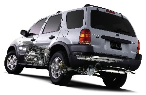
Several systems around the vehicle are impacted by two key elements: the engine does not run at all times; and the high voltage batteries need to be recharged on the drive.
The control side of a hybrid brake system contains differences, compared to its conventional cousins, to accommodate these conditions. All technical references here will be directed at 2005 to 2010 Ford Escape and Fusion Hybrid vehicles.
Regenerative Braking
A hybrid vehicle recharges its high voltage battery through the use of regenerative braking. Energy can not be created or destroyed. It can only be transformed from one form to another. We all heard that one in science class, I’m sure. In the case of conventional friction brakes, energy of motion (kinetic energy) is being transformed into heat energy, via friction, and then dissipated into the air.
With regenerative braking, instead of just wasting that energy by releasing it into the air, it is placed in a box in the back of the car and saved as stored energy. Later, that stored energy will be converted back into kinetic energy that will pour back into the body of the car.
On a hybrid vehicle, the brake pedal acts as more of a human interface to the ABS module for a request for braking. Regenerative braking is the hybrid’s first choice for braking. The ABS module “tells” the PCM or TCM (model year dependent) that a request for brakes has been made and how much braking is desired. The PCM or TCM then applies regenerative braking, via the traction motor inside the transmission, as needed.
More regenerative braking increases the amount of electrical charge generated for the HV battery at the same time it produces more drag to slow the vehicle down. During many light braking events, the rear friction brakes will be lightly applied and the front may not be applied at all until the vehicle is at a stop or near stop. For this reason, it is normal for a hybrid to wear the rear brake pads two and three times faster than the front pads.
For 2005 to 2009 models, the HV system is rated at 330V. 2010 models are now equipped with a more efficient traction motor that lowers the HV voltage requirements to 275V. For either system, you will notice bright orange wires that look like battery cables running throughout the vehicle. Those are the HV battery cables. Do not mess with those wires until you have been properly trained on that model vehicle. Simply put, those orange cables can kill you.
Electro-Hydraulic Brake Systems
The 2005 to 2008 model Escape/Mariner Hybrids use an electro-hydraulic brake (EHB) system. The EHB master cylinder is also referred to as an actuation control unit (ACU). The bore of the ACU is called a pedal feel emulator and is primarily used to simulate normal brake pedal feel for the driver. The EHB system does not have a vacuum brake booster. The pressure generated for the calipers is not, under normal conditions, the direct result of the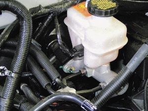 driver’s foot pedal efforts. The pedal generated pressure is normal only to stimulate a pressure sensor in the ACU that makes up the brake “request.” Normally, the fluid pressure for the wheel hydraulics is generated by the pump and accumulator in the ABS HCU and is regulated by the teamed efforts of the ABS and PCM’s logic.
Under normal conditions, the driver’s pedal efforts are displaying to the ABS module as a “request” for braking. The ABS and PCM then divide the braking effects between the traction motor (for regenerative braking) and the friction brakes as needed.
“Normal” braking for this system typically means regenerative braking is providing most of the braking and the rear friction pads provide very little braking. The front may provide very little to no braking. Of course, at a stop or near stop the friction is applied to hold the vehicle from rolling.
The higher the request for braking, the ABS module and PCM electronically calculate and decide how to apply friction and regenerative braking to meet the demand. From feather-light braking to a panic stop, all brake applications are electronically calculated and delivered from a normally operating EHB system.
Only in the event that the ABS HCU can’t function to build pressure will the driver’s pedal pressure directly provide the hydraulic pressure for the calipers. There are valves inside the HCU that allow direct passage from the pedal feel emulator chamber of the ACU, through the HCU and to the wheels. This is called “manual mode.”
In manual mode, there will be no boost so the driver will have a very hard/stiff brake pedal. Braking efforts will be very high for the driver and will likely prompt them to tow the vehicle for fear of having no ability to stop at all. The complaints of “no brakes” or “barely stops” may be the common terms used by customers whose brake system has entered manual mode (failsafe mode).
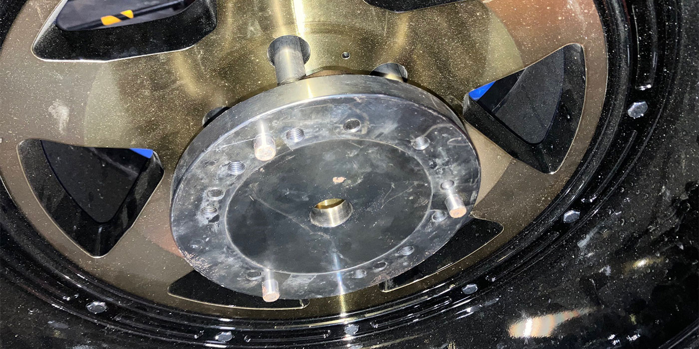
The replacement of the friction material is the same as with a conventional system, however, the ABS module does test the brake hydraulic system’s integrity by pressurizing it during key-off events, such as opening the door or whenever the dome light is activated, and again when the key is switched on.
After four minutes have passed since the key is switched off, the accumulator discharges its stored fluid pressure back into the master cylinder reservoir. Before attempting friction material replacement, you must disconnect the battery to prevent the likelihood of an accumulator discharge event, or a system pressurization, during service. In addition to battery disconnect, Ford says to remove fuses 24 (50A) and 31 (50A) in the battery junction box, though conventional wisdom says fuse removal or battery disconnect alone will prevent the system from pressurizing.
If system bleeding is required, a capable scan tool must be used for the ABS service bleed. Plus, a pressure bleeder set to deliver a continuous 35 psi is needed during the bleeding process. Do not use a vacuum bleeder on this system. This brake hydraulic system is diagonally split. The specified fluid is DOT 3.
Simulator Brake Actuator Systems
For the 2009-2010 Escape/Mariner and Fusion/Milan, the braking system has been modified. These vehicles now have a vacuum brake booster and use a Simulator Brake Actuator (SBA) as a human interface. Although the older system could be described as “brake by wire,” this system takes yet another step into the brake by wire concept, while at the same time providing a very conventional and proven failsafe mode, as well as being a little more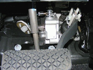 technician-friendly.
This system is equipped with a brake pedal simulator also referred to as the SBA. The simulator appears to the driver as a typical brake pedal that they are accustomed to, and is also a hydraulic cylinder loaded to provide that familiar brake pedal feel. The simulator houses a brake pedal position/angle sensor that sends a signal to the ABS module. This is an analog voltage value that the ABS module uses to determine how much braking is being requested.
“Normal” braking requests commonly only signal the regenerative braking. Unlike the older model where the rear friction brakes are lightly applied for normal braking, the friction brakes are not applied at all for normal braking with this system except for when at a near stop or a stop to hold the vehicle from rolling. To achieve regenerative braking, the ABS module sends a request to the transmission control module (TCM).
If more than normal braking is required, then the ABS module will signal the vacuum booster, via a solenoid, to apply the friction brakes by pushing a rod inside the master cylinder just like in a conventional brake system.
The brake pedal is mechanically connected by a “Z” bar and an elongated eyelet at the end of the booster rod. Under heavier than normal, but not panic, braking, the eyelet provides enough free play that the mechanical brake pedal actions do not induce force into the brake booster. This allows the ABS module to maintain control over the amount of regenerative braking versus friction braking for all braking demands from feather light to heavy, but not as strong as a panic stop.
In the event of a panic stop, the driver will be able to cram the brake pedal down fast and far enough to bottom out in the elongated eyelet, which will override the electronic controls. This will apply the friction brakes in the conventional manner.
The elongated eyelet and clevis pin attached to the brake pedal also becomes the failsafe method for brakes in the event of a critical failure. Should a critical failure occur in the electronic brake control system, there will be no regenerative braking commanded and all friction brake control will be surrendered to the driver’s foot pedal action. This will provide the feel of “head room” or free play at the top of the pedal to the driver before braking occurs while in failsafe (or manual) mode. Aside from the head room at the top of the pedal, the braking will feel almost normal after the pedal is pushed past the stack in the eyelet.
Most vehicle owners may feel safe driving the vehicle into the repair shop in failsafe mode. A soft or low pedal may be a common complaint from a customer whose brakes are in this condition. A critical failure in this system would be something that the ABS module must have to perform its duty, such as a failed pedal position sensor, vacuum or booster travel sensor, vacuum solenoid circuit or internal ABS logic, or power/ground failure to the ABS module. A non-critical failure, such as a single ABS wheel speed sensor failure, is not likely to place the system into failsafe.
The vacuum brake booster has two sources for vacuum. If the engine is running, then the engine will be that source. If the engine is not running, then an electric vacuum pump will become that source. Mounted on the booster is a vacuum sensor to monitor the amount of vacuum inside the booster. Also mounted on the booster is a booster travel sensor to provide feedback to the ABS module about the booster’s position. Both are serviceable without replacing the entire booster. The booster and master cylinder in this system have a very conventional appearance aside from the added sensors mounted on the booster, which are not very obvious at a glance.
There are no serviceable parts on the brake pedal simulator at this time. Should parts on the pedal simulator, such as the position sensor, fail, the entire assembly must be replaced.
Brake bleeding with this system also requires the use of a capable scan tool and pressure bleeder if air is in the master cylinder or the ABS HCU. Simple caliper replacement should not require those things if no air entered the master or HCU. This hydraulic system is also diagonally split. Pedal-pump bleeding should be performed with the key off so that the free play in the clevis pin and eyelet will be minimized and to prevent the ABS module from interfering. It is critical that the person operating the brake pedal pushes the pedal far enough to overcome the free play in the eyelet before judging the amount of pedal travel. DOT 3 fluid is the factory-specified fluid to use.
No specified warnings are given for pad replacement. The self-test that the older version performs is not shown to be performed by this system. However, it is considered a good practice to disconnect the battery before attempting the removal of the brake calipers on any Ford Hybrid vehicle.
I hope you’ve enjoyed the information and get the chance to profit from it soon. As every hybrid is different, play it safe and seek vehicle specific training.