 Although checking charging voltage at the battery terminals is the most popular method for testing an alternator, a charging voltage test seldom reveals less common problems like open or shorted alternator diodes, intermittent high or low charging rates, charging system wiring problems, intermittent cranking/no-start complaints or intermittent dead battery complaints.
In addition, testing charging voltage at the battery terminals does not accurately indicate the condition of a load-sensing or computer-controlled charging system.
Early Years
Early in the 19th century, Michael Faraday discovered that electricity flows through a copper wire as it passes through a magnetic field. Alternating current is produced as the wire passes through the north and south poles of the magnetic field, and the polarity of the current changes from positive to negative.
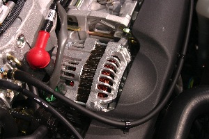
Modern alternators use a rotating magnet called a rotor to create a rotating magnetic field that is “cut” by three windings of copper wire. A positive diode is attached to one end of each field wire and a negative diode is attached to the opposite end to “rectify” the alternator’s electrical output from alternating to direct current.
The rotor’s magnetic field is created by passing a variable electrical current through a carbon brush riding against a copper slip ring that, in turn, is attached to a winding of copper wire in the rotor. Another slip ring and brush completes the rotor’s electrical circuit by grounding the current to battery negative. The voltage regulator controls the alternator’s amperage output by changing the amount of current flowing through the rotor winding.
To accomplish this, the voltage regulator must be able to accurately sense battery positive (B+) voltage through a wire attached to a B+ source. To complete the circuit, the voltage regulator must also be thoroughly grounded to battery negative (B-). The regulator must also have a key-on source for B+ voltage to activate the rotor.
Integrating Voltage Regulators
Early charging system configurations located the voltage regulator on the fender well or firewall. As the vehicle ages, rust forms between the body panels upon which the regulator is mounted, which tends to create an excessive electrical resistance in the B- circuit between the voltage regulator and battery.
Because excessive resistance might cause the voltage regulator to sense a low charging voltage, the regulator might cause an over-charging condition by increasing current flow to the rotor.
Over-charging is usually indicated by a sulfurous smell emanating from the battery and overheated electrolyte boiling from the battery cell caps or cell vents.
Engineers initially addressed the voltage-sensing problem by using a ground wire to connect the regulator directly to the alternator.
More recently, the voltage regulator has either been integrated into the alternator assembly or has been moved from the alternator to the powertrain control module (PCM). With the regulator now incorporated into the PCM, engineers can also vary alternator output according to vehicle operating conditions.
Computer-Controlled Systems
In many cases, it’s advantageous to connect a scan tool to the vehicle’s diagnostic connector before performing a pin-out test on the charging system. Notice I said “many cases;” in fact, it is probably best to start your check that way.
Depending on the scan tool’s capabilities and the PCM’s programming, the scan tool can reveal electrical system voltage, a trouble code indicating a problem within the charging system, the state of battery charge or the degree of pulse modulation being administered to the rotor assembly.
The scan tool may include a bi-directional control that allows the technician to control the output of the alternator for testing purposes. In the case of any 1996 and newer vehicle, attaching a scan tool might be a very important first step in diagnosing a charging system problem.
Now we’ll turn to the battery, which builds an electrical resistance as it approaches full charge. As resistance increases, so does charging voltage. In the rare case of an electrical short-circuit in the battery plates, the battery may offer little, if any, resistance to current flow from the alternator. In essence, the alternator may overheat and eventually destroy itself trying to charge a battery with shorted plates.
At the other end of the scale, battery plate sulfation caused by the battery being partially discharged for a long period of time will create an excessively high resistance to an incoming charge from the alternator.
Although sulfated batteries maintain high charging voltages, they fall short on the capacity needed to meet peak electrical demands such as excessive cranking or key on, engine off accessory operation.
Adjustable carbon pile load testing, conductance testing and specific gravity testing of the electrolyte in the battery’s cells can measure battery condition. Because low temperatures greatly reduce battery capacity, the core temperature of a battery must be at room temperature before a carbon pile test can be performed.
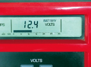
In brief, adjustable carbon pile load testing is a 15-second test that discharges a fully charged battery to a specified test load or to one-half of its cold cranking amperage (CCA) rating. Before the load test can begin, the battery should display at least 12.4 volts at its terminals (see Photo 1). At the end of the test, the battery should display a minimum of 9.6 volts at its terminals.
A conductance test uses alternating voltage to measure cell resistance. Some testers have issues with battery temperature, resistance at the battery terminals and a low state of charge, so it pays to be familiar with the characteristics of the tester being used.
Last, if the battery has removable cell caps, the specific gravity of each cell should be at least 1.250 with no more variation than 0.050 between the cells. Keep in mind that most specific gravity testers are designed to compensate for temperature variations in the electrolyte.
On rare occasions, a battery can develop an intermittently open or shorted cell. If the battery is questionable, a known good battery should be temporarily substituted for testing a charging system.
Alternator Testing
The voltage regulator will generally vary charging voltage from about 13.8 volts on warm days to about 14.8 volts on sub-zero days. At room temperature, an alternator should charge about 14.2 volts.
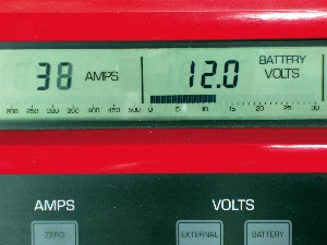
Adjustable carbon pile testers can be used to test alternator output and drive belt condition. When using a carbon pile tester, load the alternator until the battery voltage reaches 12.0 volts (see Photo 2).
Keep in mind that, while most modern alternators produce nearly 100 amps at idle speed, amperage output is generally rated at 2,500 rpm engine speed. When measured as close to the alternator B+ terminal as possible, the amperage output of the alternator should meet specifications.
If the alternator drive belt squeals approaching maximum output, the alternator drive belt and pulley should be inspected for glazing and wear. If the amperage output doesn’t meet specifications, suspect an open diode or worn brushes.
Many carbon pile testers have an “AC ripple” feature indicating when a shorted diode is “leaking” alternating current into the charging system.
The diode test also can be performed by setting a digital volt-ohm meter to AC voltage and attaching the positive lead directly to the alternator B+ terminal.
Note: The maximum level of alternating current (AC) voltage present in a charging system has changed over the years. The past rule of thumb had generally been 0.250 AC volts. However, equipment manufacturers now recommend 0.500 AC volts as a real-world limit. Some alternator rebuilders report that the presence of 1.0 AC volt isn’t unusual for heavy-duty charging systems.
While a higher level of AC voltage doesn’t necessarily affect the functionality of the alternator, it can interfere with the operation of a vehicle’s on-board electronics. Because higher accessory loads and higher output alternators have increased the presence of AC voltage in the charging system, a technician shouldn’t be surprised if he discovers higher levels of AC voltage in future applications.
A reading of 0.8 to to 0.10 volts is normal. Keep in mind that excessive AC ripple can cause performance issues in the PCM and related modules.
Watch for Intermittents
An intermittently high charging rate might store a trouble code in the PCM or might be indicated by repeated failures of the high-beam headlamp bulbs. Low-state-of-charge issues are indicated by intermittent cranking, no-start complaints in sub-freezing temperatures, intermittent dimming of headlamps or battery sulfation.
In most cases, a set of sticking or worn alternator brushes, a broken field control wire, corroded battery cables or a bad connection at the alternator or battery will cause an intermittent low-state-of-charge problem.