Troubleshooting mass airflow (MAF) sensor problems can become a major headache for diagnostic technicians because the failure is usually one that involves a calibration error rather than an outright electrical or mechanical failure. Because calibration errors tend to be “gray-area” types of problems, let’s begin by looking at the basics of how a “hot-wire” MAF sensor measures airflow through an engine running at various speeds and loads.
Basic Principles
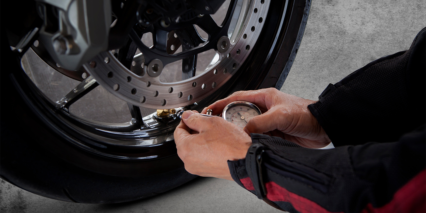
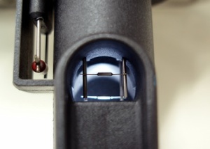
In general, a “hot wire” MAF sensor produces an input to the PCM when a low-amperage electrical current is passed through a metal-film resistor suspended in the MAF’s air stream. The amperage flow through the resistor changes because the electrical resistance of the resistor is responding to the cooling effects of rapidly moving air. This variation in current flow, which is a base data input, is then translated into a voltage or frequency signal that is sent as a secondary data input to the PCM. In some applications, the PCM translates the base data input into a grams-per-second (GPS) data line indicating the metric weight of the air flowing into the engine. See Photo 1.
Some MAF sensors also include an intake air temperature (IAT) sensor that helps the PCM calculate air density. In other MAF designs, the IAT is located downstream from the MAF sensor. Although there are different configurations of MAF sensors, most current hot-wire MAFs share the same basic operating principles.
Factors Affecting Calibration
“False air” leaking through cracks in the ducting that connects the MAF to the throttle body is a common problem affecting MAF sensor calibration. In most cases, false air leaks will cause low-speed stalling or rough-idling complaints.
Contamination of a MAF’s resistors is, by far, the leading cause of MAF calibration errors. Oil, dirt or even paper filaments detaching themselves from poor-quality air filters can accumulate on the metal-film resistors suspended in the intake air stream.
In most cases, contamination tends to insulate the metal-film resistor from the air stream, which makes it run hotter than normal. This generally forces the MAF to underestimate the engine’s intake airflow. On the other hand, a large particle stuck on the resistor, such as an insect or particle of vegetable chaff, can cause the metal-film resistor to radiate more heat than it should, causing the MAF to overestimate intake airflow. See Photo 2.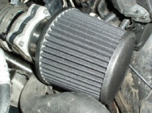
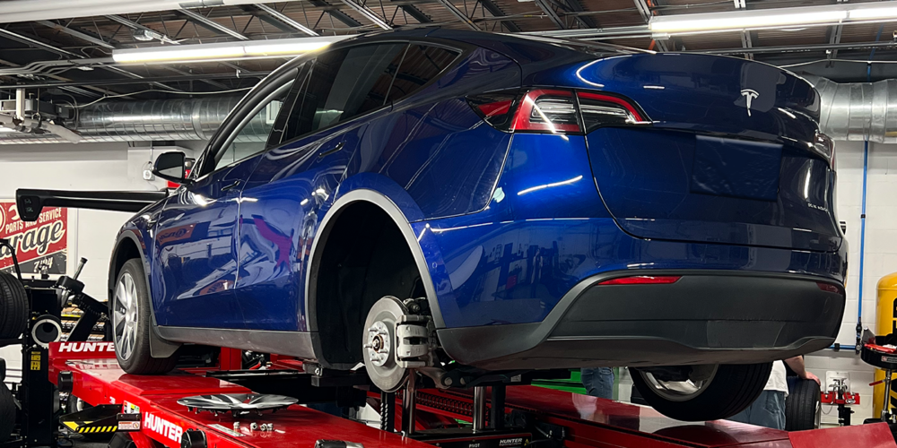
Turbulence in the intake air stream can also affect MAF sensor calibration. For example, a reverse pulse wave in the intake duct caused by a poorly seating intake valve or cylinder misfire can momentarily reverse the airflow into the MAF. While diagnosing such problems are beyond the scope of this text, remember that intake manifold tuning valve failures, valve-timing problems, and restricted intake or exhaust systems usually reduce airflow through the engine. See Photo 3.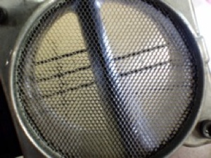
At the other end of the turbulence issue, remember that the original equipment air filter and intake air box are specifically designed to reduce turbulence into the MAF sensor assembly. Replacing the original equipment air intake system with various customized intake systems can increase air turbulence and, thereby, cause a calibration error resulting in an engine performance complaint.
Diagnostic Strategies
It’s obvious that MAF calibration errors can be difficult to diagnose because the PCM’s programmed diagnostic strategy often doesn’t have enough data inputs from other sensors to rationalize or analyze MAF sensor performance. Consequently, many master diagnostic technicians have devised a number of diagnostic strategies that, in one form or another, can be used to diagnose MAF calibration errors. With “indicative” saying “maybe” and “definitive” saying “pass or fail,” I’ll give you my opinion of how effective each method of analyzing MAF performance might be.
Grams Per Second
Off the top, I’ll say that a few entry-level Asian nameplates use the GPS method to analyze MAF performance. For example, an OE procedure might include GPS readings at idle, at 1,500 rpm, and perhaps at 2,500 rpm, to analyze MAF performance. Some aftermarket trainers have also suggested that the GPS number on a good MAF will equal the engine’s displacement in liters at idle speed. In other words, 3 GPS at idle would be correct on a 3L engine. According to my own experience, grams-per-second is an indicative, rather than definitive, analysis of MAF performance.
Voltage and Frequency
Voltage tests are similarly more indicative rather than definitive. In many applications, idle speed voltages should hover around 0.7 volts. The “air gulp” test uses a labscope to display the MAF output voltage increase during a snap-throttle test, and should show the voltage rising from about 0.7 to a higher voltage that’s dependent upon the condition of the MAF and of the engine and exhaust system. In my opinion, voltage and frequency testing yields indicative rather than definitive results when attempting to diagnose MAF calibration problems.
VE Testing
Volumetric efficiency (VE) testing assumes that the indicated GPS should agree with the calculated air volume or GPS flowing through the engine. A metric VE calculator using grams-per-second airflow can be located by using an Internet search engine. Keep in mind that VE calculators applied to naturally aspirated, stock engines generally produce definitive results.
Calculated Values
Some on-board diagnostic systems display a calculated barometric pressure value and/or a calculated load value. Calculated load is a value produced by the PCM by rationalizing inputs from (among others) the MAF, engine speed and throttle position sensors.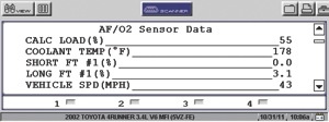
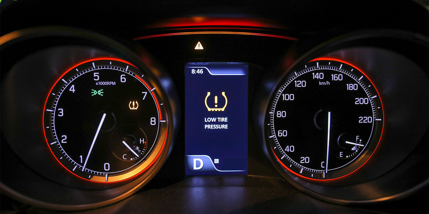
While calculated load varies among most vehicles, the calculated load at wide-open throttle at higher engine speeds should be at least 80%. If recorded calculated load can be compared with an identical engine configuration, so much the better. Since it’s less likely that the throttle position and engine speed inputs are faulty, calculated load values of less than 80% are indicative of a calibration problem with the MAF sensor or of a restriction in the engine’s fuel, air intake or exhaust system. See Photo 4.
| Why Do MAF Sensors Fail?
Contamination is a key reason why MAF sensors fail and require replacement. As air, dirt and other debris get into the sensor, the parts become contaminated and fail. Drivers often notice sluggish performance, rough idling, poor acceleration or even stalling. There mayalso be a more frequent need to refuel. Contamination could even occur as early as at every 18,000-25,000 miles,depending on the vehicle model. For example, with small or compact cars, the MAF sensor can clog quicker, as it is placed in a smaller engine bay subjected to more risk in critical areas (oil vapor flows andcombustion debris). In this case, a replacement becomes the equivalent of a long drain oil service…it almost becomes a service-style repair. Other common failure problems include: A problem with the mass air flow sensor often causes the ”check engine” or ”service engine soon” light in the vehicle instrument panel to illuminate. These lights come on when the engine computer detects some fault in one of the components of the emission control system. Symptoms of failure include: How to troubleshoot a MAF sensor: |
Some applications also use the MAF, TP and engine speed inputs to estimate barometric pressure (BARO). The BARO value might be expressed as a frequency (Hz) or as inches of mercury (“Hg). In any case, if the recorded barometric pressure isn’t equal to local barometric pressure, it’s indicative of a calibration problem with the MAF sensor or a restriction in the engine’s intake or exhaust system.
Basic Fuel Trim Analysis
Engineers program a “fuel map” into the PCM that indicates the exact amount of fuel required to meet hundreds of different operating conditions. Since this fuel map is monitored by the oxygen or air/fuel ratio (AFR) sensors, fuel might need to be added or subtracted to bring the oxygen or AFR sensors back to “center” or to a chemically correct stoichiometric value. More fuel being added to the programmed fuel map value results in a positive “fuel trim” number, while subtracted fuel results in a negative fuel trim number.
Most MAF calibration problems are indicated by the classic P0171 and P0174 DTCs. Fuel trim analysis can be tricky because intake manifold vacuum leaks and insufficient fuel supply can also set these DTCs. Negative fuel trim numbers caused by minor intake vacuum leaks generally disappear under heavy engine loads. Positive fuel trims caused by leaking fuel pressure regulators and injectors also tend to disappear under increased engine loads.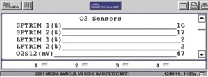
Short-term fuel trims reflect the immediate demands of the engine, while long-term fuel trims are an average of short-term fuel trims. Fuel trims of plus or minus 10% are considered normal, while plus or minus 25% will generally set an appropriate DTC. See Photo 5.
But negative fuel trims at higher engine loads can also be caused by dirty MAF sensors or by low fuel pressures. Consequently, it’s important to eliminate fuel delivery issues by testing fuel pump pressures and volumes before assuming that the MAF sensor is truly defective. In most cases, a defective MAF sensor will reveal itself through a combination of the evaluation techniques mentioned above.
Last, it’s important to understand that the metal film resistors generally lose their calibration due to normal wear and tear. While a careful cleaning might restore a MAF sensor’s basic calibration, that level of calibration might not pass one of the many different exhaust emissions tests enforced throughout the U.S. So, if you’re in doubt, it’s best to always replace a MAF sensor suffering from a suspected calibration defect.