To put exhaust restriction diagnostics in perspective, tire dealers and auto repair shops have been dealing with loss-of-power complaints caused by exhaust restriction since catalytic converters were popularly introduced in 1974. Early “cats” experienced frequent failure because the carbureted engines of that era were notorious for poor fuel control. Raw fuel from a sticking choke or over-rich fuel injection could combine with excess air injection to overheat the catalytic converter. This fatal combination would usually cause the converter to internally melt or partially collapse, which would then cause a varying degree of exhaust restriction.
During that era, the standard diagnostic method for testing exhaust restriction was to test for a decrease of intake manifold vacuum between idle speed and a steady-throttle 2,500 rpm value. If both readings were nearly the same, the converter wasn’t restricted. If the vacuum reading at a steady 2,500 rpm dropped by more than 10% from idle values, the converter was likely restricted. An alternate method was to see if engine performance would improve by disconnecting the catalytic converter from the exhaust manifold. Such methods are often lacking when diagnosing modern engine management systems.
A Word About Volumetric Efficiency
Because volumetric efficiency is a measure of the ability of the engine’s intake, valve timing and exhaust systems to fill an engine’s cylinders with air, it’s particularly useful to understand the concept when diagnosing exhaust restriction. Obviously, as exhaust ¬restriction increases, volumetric efficiency decreases.
An older engine with a less efficient intake system might achieve an 85% fill rate, while a modern design with a tuned intake and variable camshaft timing might exceed a 100% fill rate. Depending upon boost pressure, a turbocharged or supercharged engine can, of course, achieve much higher cylinder fill rates.
In the strictest sense, the calculated load value displayed on a scan tool data stream is the most direct indicator of an engine’s volumetric efficiency. But, because calculated load values vary considerably among different engine designs, it’s always best to compare any calculated load data with known-good values.
Another method of calculating volumetric efficiency is to compare the engine’s airflow in grams per second with the numbers generated by a volumetric efficiency calculator. Entering “volumetric efficiency” into your computer’s search engine can access several volumetric-efficiency calculators. Some nameplates actually specify a grams-per-second airflow rate at different engine speeds to aid in diagnosing the mass air flow (MAF) sensor itself.
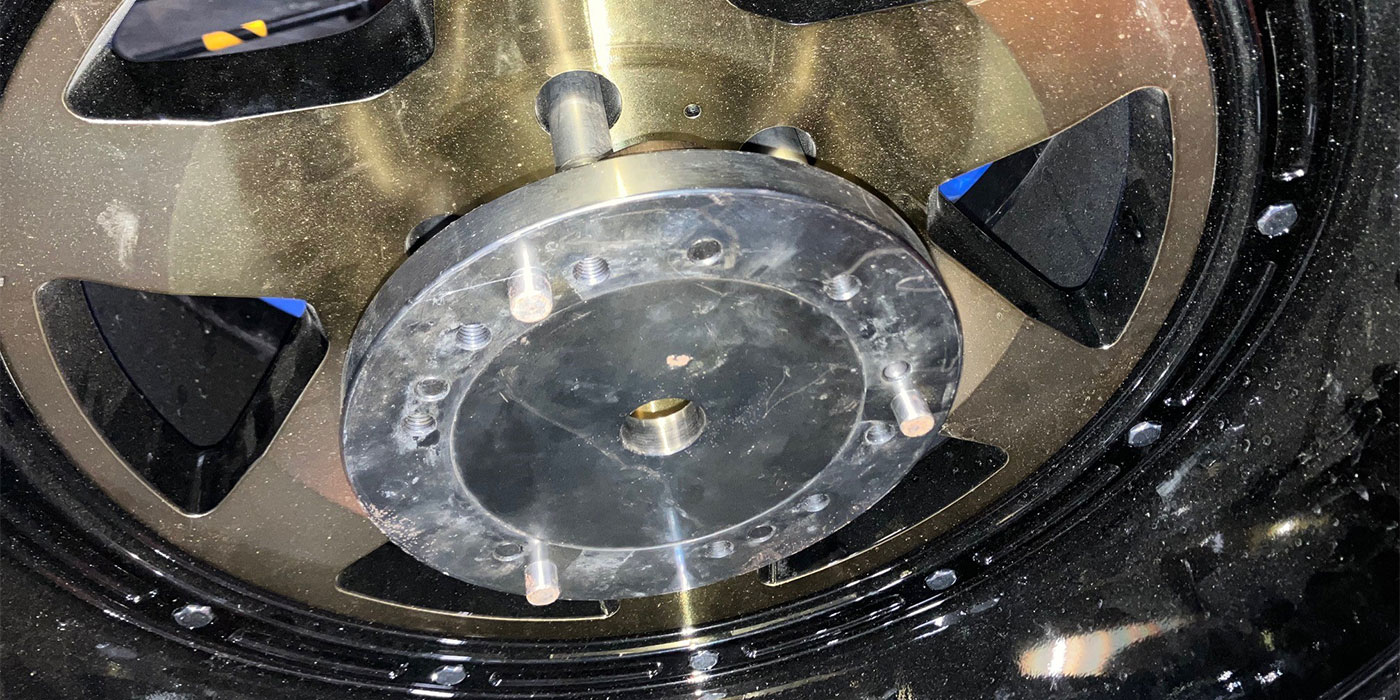
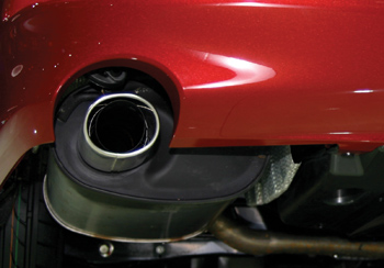
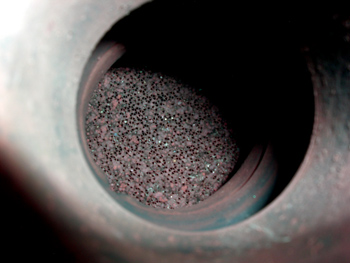
In any case, it’s important to remember that the only absolute in diagnosing exhaust restriction is that there are no absolutes. For example, the substrate in a catalytic converter can break apart, causing a partial intermittent exhaust restriction. Similarly, the substrate can be coated with contamination that causes any degree of exhaust restriction, ranging from zero to 100%. Because the context of any exhaust restriction diagnostic process is situational, the information I’ve outlined below should be interpreted as indicative, rather than definitive, in nature. See Photo 1.
Speed Density System Diagnostics
Speed-density systems found in older vehicles are designed to provide a calculated, rather than direct-reading, value for engine airflow. Speed density calculations generally include data from the throttle position, manifold absolute pressure (MAP) and engine speed sensors.
Keep in mind that the MAP value will begin to equal the atmospheric pressure value as the throttle opens and load increases on the engine. The PCM responds to the increased MAP value by richening the air/fuel ratio. If the exhaust is restricted, the MAP value will equal atmospheric value as soon as the throttle is opened and the engine fails to accelerate. The engine generally tending to run rich and lose power are symptoms of exhaust restriction in a speed-density system.
In most cases, exhaust restriction in speed-density systems can be diagnosed by looking for a significant loss of intake manifold vacuum at higher constant-throttle engine speeds. An alternative method is to directly measure exhaust gas pressure by removing the oxygen sensor and installing a backpressure sensing tool. Any positive exhaust pressure reading at idle indicates exhaust restriction. Any significant gain in exhaust gas pressure as the engine is accelerated also indicates exhaust restriction.
Mass Air Flow System Diagnostics
Because a MAF sensor provides a direct reading of engine airflow, the symptoms produced by high exhaust gas pressures differ dramatically from those of speed-density systems. MAF sensors produce either a direct voltage or a square-wave frequency signal to the PCM. The PCM might then simultaneously display either the voltage or frequency signal along with a grams-per-second conversion on the scan tool data stream.
When a MAF system is exposed to an exhaust restriction, the MAF immediately indicates to the PCM that airflow through the engine is reduced. The PCM then re-establishes a chemically correct air/fuel ratio by adjusting the weight of fuel to the weight of air flowing through the engine. The symptoms of a ¬restricted exhaust on a MAF-equipped engine will be a noticeable loss of power rather than a rich fuel condition.
Of course, here again is the chicken-and-egg problem of differentiating between a bad MAF and a restricted exhaust. In general, a contaminated MAF over-estimates fuel (rich) at low speeds and under-estimates fuel (lean) at high speeds. On many nameplates, simply disconnecting the MAF will eliminate a MAF-related problem, whereas it won’t eliminate a restricted exhaust problem.
Data Stream Indicators
If a calculated load value appears on your scan tool, that value will be lower on an engine operating with a restricted exhaust. In general, calculated engine load values should be 85% and above. While a 65% value wouldn’t be definitive, it would be an important indicator of exhaust restriction.
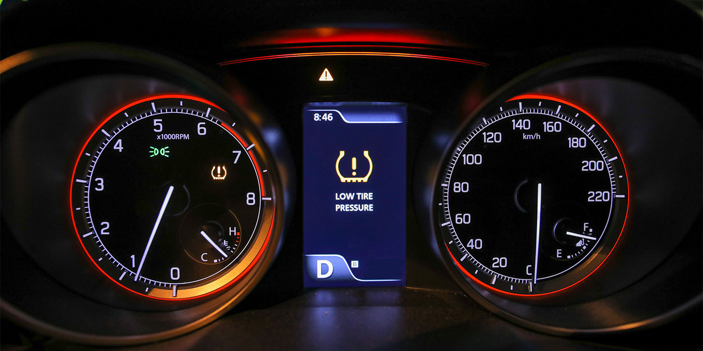
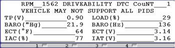
Similarly, if the PCM uses data from the MAF sensor to calculate a barometric pressure value, that calculated barometric value will be lower than normal if the exhaust is restricted. In most cases, the PCM calculates the barometric value at a specific engine speed and throttle opening. A typical calculated baro value would be 159 Hz at sea level and approximately 138 Hz at 8,000 feet altitude. If the calculated value is 138 Hz at sea level, the actual airflow in relation to engine speed and throttle opening is equivalent to that value at 8,000 feet altitude. See Photo 2.
If one of two primary or upstream converters feeding into a single downstream converter becomes restricted on a V-block engine, the engine might develop misfire codes on the bank with the restricted converter. If an upstream converter is restricted, the short- and long-term fuel trim data numbers will not be balanced from bank-to-bank. In some cases, the left- and right-bank fuel trim numbers might range from extreme positive to extreme negative due to an upstream exhaust restriction.
Last, a restriction caused by a catalytic converter failure might not be accompanied by the P0420-P0430 DTCs, which indicate that converter isn’t efficiently oxidizing exhaust pollutants. And, keep in mind that, on rare occasion, a collapsed double-wall exhaust pipe or restricted muffler can cause an exhaust -restriction, rather than a failed catalytic converter.
Valve Timing Restriction
While I can’t offer a complete discussion of valvetrain design and diagnosis in this space, it’s important to know that valve-timing problems on a modern overhead camshaft engine can seriously affect volumetric efficiency and, therefore, mimic the symptoms produced by a restricted exhaust system.
In most cases of incorrect valve timing on a V-block engine, cranking and running compression will differ from bank-to-bank. If you’re an advanced diagnostic tech, a difference in bank-to-bank cylinder running pressures can also be detected by using a cylinder pressure transducer coupled to a labscope. If the camshaft in question is equipped with a camshaft position sensor, a crankshaft-to-camshaft synchronization error might be detected and a related DTC will likely be stored.
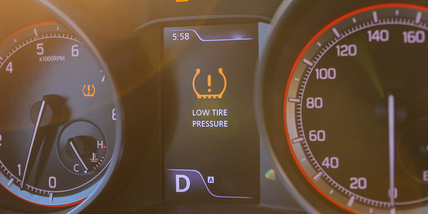
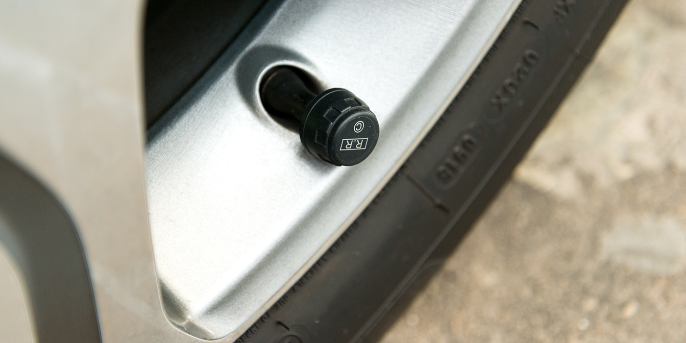
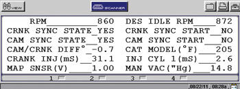
If the engine is equipped with variable valve timing, the valve-timing sensor on the camshaft in question will cause a valve timing-related code to be stored. Keep in mind that the camshaft position sensor and valve-timing sensor serve two distinctly different functions and provide very different streams of data to the PCM and, therefore, will store different DTCs. See Photo 3.
As for symptoms of incorrect camshaft timing on engines not equipped to store related codes, remember that advanced camshaft timing reduces power at high engine speeds, while retarded camshaft timing reduces power and throttle response at low engine speeds. Retarded camshaft timing generally reduces cranking compression and intake manifold vacuum, while advanced camshaft timing generally increases cranking compression and intake manifold vacuum.
Diagnostic Summary
Many advanced technicians can diagnose a restricted exhaust system by observing and comparing scan tool data or by measuring cylinder pressure with a pressure transducer and labscope. Consequently, the diagnostic procedure chosen depends very much upon the skill level, system knowledge and tooling of the individual technician.
A simple exhaust system backpressure test remains the most reliable method of locating an exhaust ¬restriction. In most cases, a road-test value and a snap-throttle value will determine the extent of the exhaust restriction. If the amount of restriction is marginal, the exhaust might pass a backpressure test, but also might cause a lack-of-power complaint while climbing steep hills. In this case, paying attention to calculated load, the MAF sensor and other volumetric efficiency indicators will furnish valuable clues to confirming suspected exhaust restriction problems.
In any case of suspected exhaust restriction, ¬remember that a catalytic converter is covered by a federally mandated eight-year, 80,000-mile emissions system warranty. For that reason, any suspected catalytic converter restriction problem should be referred to an authorized dealership if it appears to be a warranty repair.