When we’re attempting to diagnose a charging system failure, it helps to think of the battery’s state of charge (SOC) as a type of checking account. 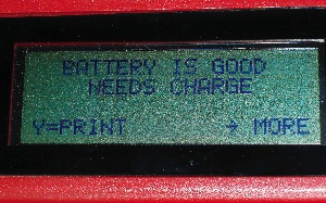 If we overdraw our account by writing one huge check (i.e. leaving the headlamps on overnight), we wake up the next morning with an engine that won’t crank. Or, if we overdraw our account by writing many small checks (i.e. short-trip driving, key-on, engine-off accessory use) and not balancing our account at the end of the day, we again are greeted with a slow-cranking engine and an overdrawn charging system account.
A battery with a “balanced” checking account will maintain 12.6 volts across its terminals with the surface charge removed (See Photo 1). Surface charge is any terminal voltage higher than 12.6 volts. Turning on the headlamps for a few minutes is the quickest way to remove surface charge. If the voltage dips below 12.6 volts with the surface charge removed, a fully charged battery in good condition will quickly recuperate and return to 12.6 volts. For the sake of simplicity, I’m going to illustrate basic alternator testing tips throughout the following text using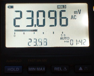 a 1997 Nissan Maxima with a conventional integral alternator/voltage regulator assembly.
Failure Patterns
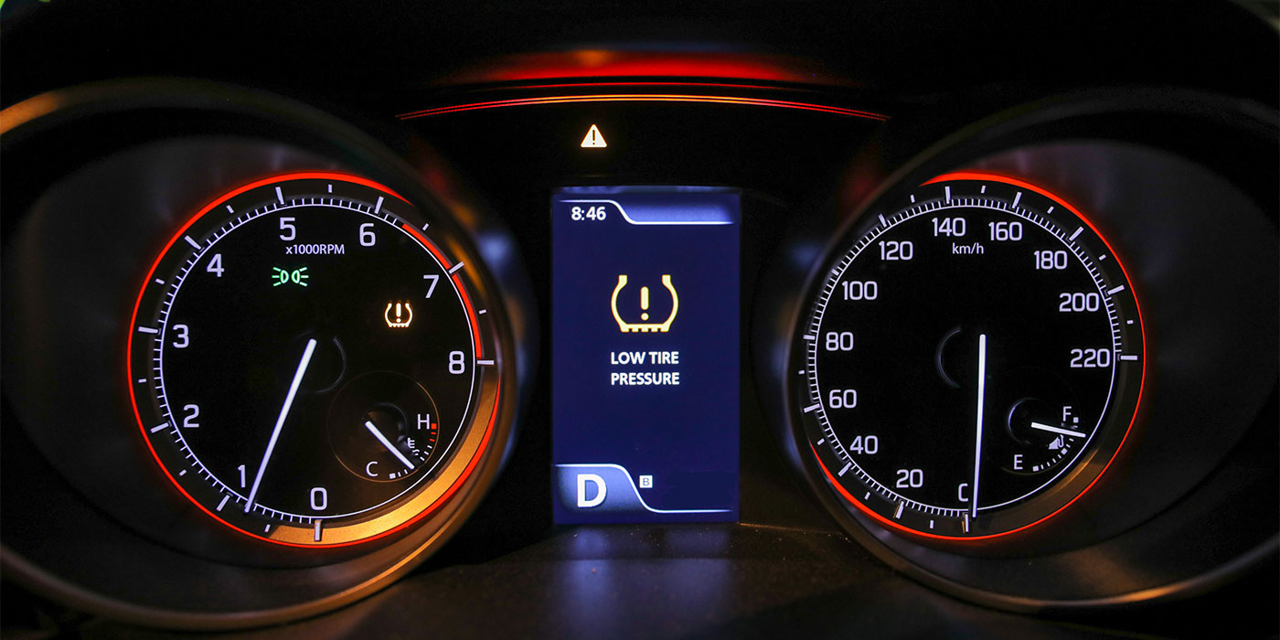
The most common alternator failure is the glaring red “bat” light indicating a catastrophic alternator failure. Catastrophic failures are usually due to an alternator malfunction, but can also be caused by a faulty drive belt or blown fuse. A related alternator failure is the battery warning light illuminating on a random or intermittent basis because the alternator’s carbon brushes are sticking in their holders or are worn out.
Another common failure is the alternator bearings becoming dry or pitted, which causes a rough, growling sound to emanate from the alternator case. Although the noise might be intermittent at first, it will worsen with mileage. In most cases, bearing noise can be detected by using a common shop stethoscope to pinpoint the source of the sound.
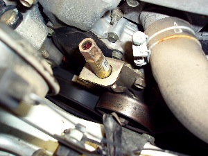
A relatively rare failure is when one or more of the alternator’s three pairs of positive and negative voltage diodes develop a short or open-circuit failure. Because the diode’s job is to rectify alternating current (AC) into direct current (DC) that can be stored in a lead-acid battery, AC voltage begins to “leak” into the vehicle’s electrical system when a diode fails. See Photo 2.
This AC leakage causes an electrical “ripple” effect that can cause unpredictable problems with the operation of the vehicle’s on-board electronic systems. In this case also, the alternator generally loses about one-third of its charging capacity. Alternating current generally can be detected at the battery by connecting a multimeter set to the AC voltage position.
Battery Testing
Charging systems diagnostics is not for the untrained technician. Always remember that a charging battery produces explosive hydrogen gas. Shorting the battery terminals together with a wrench or other metallic object, or exposing a battery to a source of ignitions such as a flame or spark, can produce a catastrophic explosion.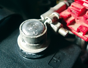
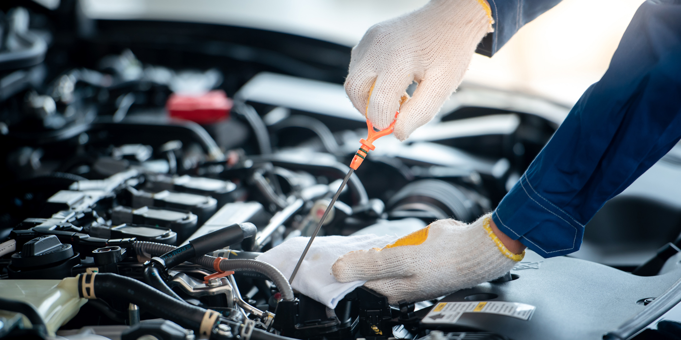
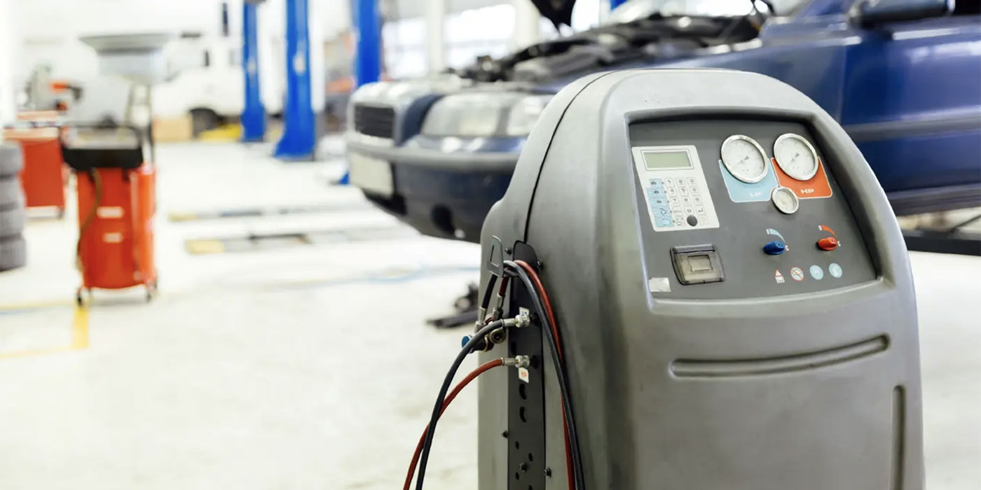
Because the alternator’s charging rate is governed by the battery’s state-of-charge (SOC), it’s important that the battery condition is tested before the alternator is replaced (See Photo 3). In general, most conventional alternator systems produce about 14.2 volts at the terminals on a fully-charged battery at 70 degrees F ambient temperature. Keep in mind that charging voltage increases at colder temperatures and decreases at warmer temperatures.
Because normal charging voltage can’t be achieved on a battery with a bad cell, the alternator will over-charge the remaining cells and boil the electrolyte. At the other extreme, a battery that is sulfated due to being under-charged or not seeing constant use will maintain normal charging voltages. The symptoms of a sulfated battery are that it charges very quickly and produces a very low amperage discharge rate. See Photo 4.
Two diagnostic methods currently are used to measure battery condition. Modern conductance testers measure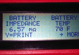 electrical resistance in the battery by applying a mild alternating current to the battery terminals. See Photo 5.
A more conventional method of determining battery condition is to use an adjustable carbon pile load tester to discharge the battery at one-half of its rated cold-cranking amperage capacity (CCA). The battery should maintain at least 9.6 volts at its terminals after being discharged for no more than 15 seconds. See Photo 6.
Because new batteries typically test as much as 25% higher than their rated capacities, a new battery with a bad cell can occasionally pass both a conductance and a load test. A specific gravity tester can be used to detect a bad cell if the battery has removable cell caps. If in doubt, always substitute a known-good battery for accurate alternator testing.
Charging System Configurations
Early configurations generally located the voltage regulator on the firewall or fender well. Because corrosion usually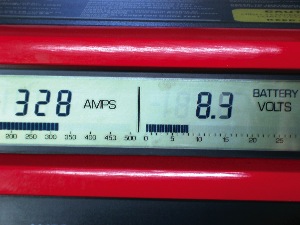 increases the electrical resistance of the ground circuit through the body panels, the voltage regulator senses less than actual B+ voltage, which causes an overcharge at the battery.
To eliminate this possibility, many veteran technicians install an auxiliary ground wire from the regulator base to an alternator or engine ground. Alternator condition can generally be tested in these systems by disconnecting the voltage regulator and “full-fielding” the alternator. Always consult an applicable service manual before attempting a full-field test.
The most common charging system configuration is like the one on our 1997 Maxima, which integrates the voltage regulator with the alternator. Alternators with integral voltage regulators can often be full-fielded by inserting a metal pin through the alternator case to ground the B-brush on the alternator. Because it’s generally not cost-effective to replace integral voltage regulators, most shops replace the alternator as an assembly.
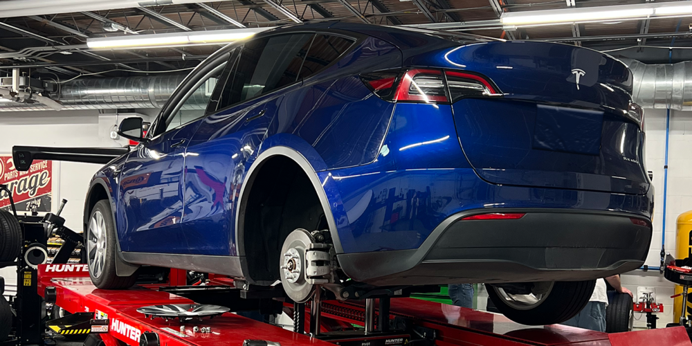
alternator’s charging rate. To achieve maximum fuel economy and minimum exhaust emissions, the PCMs in some configurations may charge the battery only during specific operating conditions. Remember that, because theseThe latest configuration of charging systems uses the vehicle’s Powertrain Control Module (PCM) to control the systems are constantly measuring the battery’s state-of-charge (SOC), the battery should always be in good condition and fully charged. See Photo 7.
The best practice in diagnosing alternators on late-model imports is to connect a professional scan tool to measure charging voltage and to retrieve any possible charging system trouble codes. In many cases, the scan tool can be used to activate or control the field current to help evaluate the alternator’s output. When diagnosing these systems, always follow the auto manufacturer’s recommended test procedures.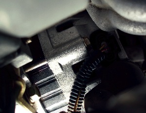
Always keep in mind when diagnosing alternators that to prevent damaging on-board electronics, the maximum allowable charging voltage in most systems is 17 volts. For that reason, I personally prefer not to “full-field” an alternator, even when that option is available.
the fusible link stretches when pulled or has no continuity, it should be replaced. Similarly, always use a DVOM toInstead, I use a DVOM to measure available voltage at the alternator. If, for example, battery voltage isn’t available at the B+ terminal of the alternator, check the condition of the fusible link connecting the alternator to the battery. If test the continuity of the alternator’s field fuse or to check for the presence of key-on field current at the alternator field connector. See Photo 8.
Load-Testing Alternators
Unless otherwise specified, the best method for testing conventional charging systems is to use an adjustable carbon pile tester to measure battery discharge rate and alternator charging rate.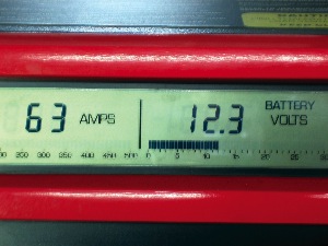
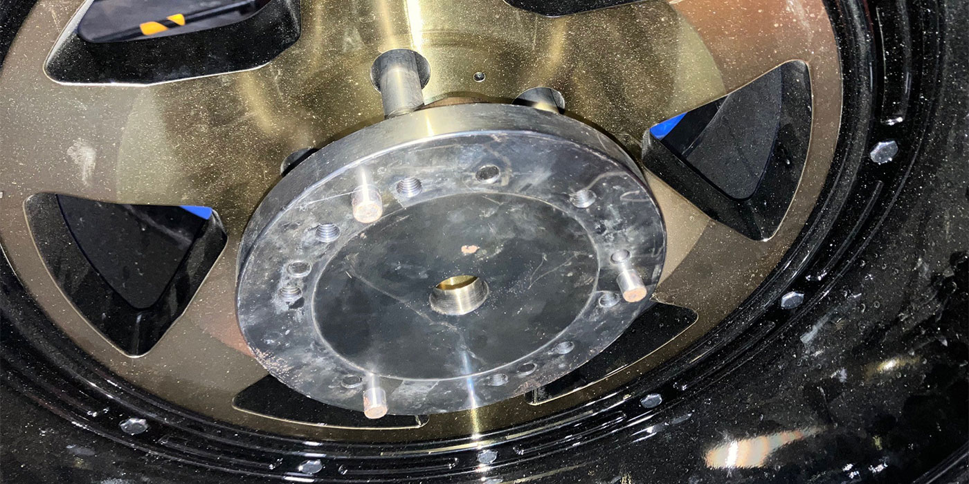
Although load-testing an alternator provides a quick way to test for drive belt slippage, keep in mind that an alternator can easily be overheated when testing for maximum output during low-speed operation (See Photo 9).
The rated output for our ’97 Maxima equipped with the LR 1100-709 alternator is 35 amps at 1,300 rpm, 85 amps at 2,500 rpm and 105 amps at 5,000 rpm. Because carbon piles are designed only for 15 seconds of operation without overheating, keep the duration of load-testing as short as possible.
Summary
The most important issue in modern alternator testing is to identify and fully understand the operation of the charging system in question. Never jump to conclusions and never skip steps in the diagnostic process (See Photo 10). And, always remember that the heart of our charging system “checking account” is the battery itself.