rticles/12_01_1999/969014jpg_00000050227.jpg” border=”0″ ” align=”right” alt=”figure 4: using an inductive wand adapter to read secondary ignition. this makes for easy data gathering especially around obstacles. “/>
Exceptions to this are Delphi coils found on Chevrolet Trailblazers, which connect the chassis ground terminal to the bolt eyelet.
For three-wire coils, the PCM determines the dwell and timing but does so indirectly. The PCM provides a pulse command, which signals the electronics within each coil to switch.
The duration of the command pulse equals the dwell time of the coil.
See Figure 5.
I tested several Nissan, Acura and Mitsubishi vehicles and was surprised to find that a coil connector could be unplugged and not trigger coil-related trouble codes.
This was confirmed on multiple trips. Eventually, a misfire code would set and illuminate the MIL but without hint that a coil was to blame. The command pulse is worth checking using a lab scope. The majority of vehicles use a 5-volt pulse; however, a few use full charging voltage.
If a coil is unplugged, thereby eliminating electrical load, the signal will be full value, typically 5 volts. However, on a connected and loaded circuit, the voltage is closer to 4 volts. Pay attention to the amplitude and shape of the signals as coil issues can be revealed in the pattern.
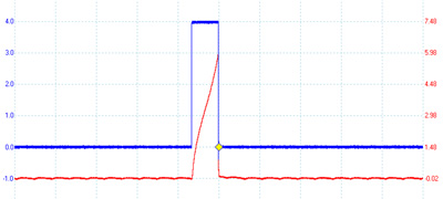
See Figure 6.
Because internal electronics control primary coil switching, primary resistance cannot be directly measured.
Depending upon internal controls, secondary resistance may not be measured either.
With resistance checks and coil primary voltage patterns unavailable, primary current measurement is a good choice.
Again, the best spot is a common relay or fuse that feeds all coils.
See Figure 7.
Peak current values and patterns differ between vehicles, so comparison between cylinders is the applicable measure.
Coil secondary voltage patterns can also be measured as mentioned regarding two-wire coils.
Four-Wire Coils
There are two popular flavors of four-wire ignition coils. The first can be found on Toyotas.
Three of the wires are power, chassis ground and PCM command signal, just like the previously mentioned three-wire coil.
The fourth wire is a diagnostic circuit known as “IGF” and is run in parallel with all of the ignition coils. The PCM provides a 5-volt bias voltage on this circuit. 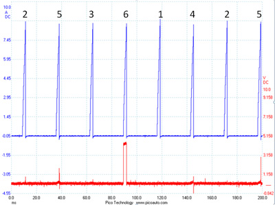
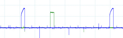
Each coil has integral diagnostic detection electronics, and when a coil successfully fires, it briefly pulses the IGF circuit to ground as a confirmation pulse to the PCM.
To test this system, I removed the chassis ground wire from an ignition coil and monitored both the command pulse and diagnostic circuit.
Sure enough, the command pulse was provided, but without diagnostic ground pulse for that cylinder.
See Figure 8.
The PCM quickly set a coil diagnostic code.
The second version of four-wire coil is found on some General Motors products. These coils utilize power, chassis ground, a PCM command signal known as “IC” and a fourth wire known as low reference. Low reference is a treated, “cleaner” ground that is sourced through the PCM. 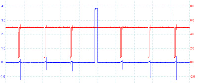
From measuring current on each circuit, it appears that low reference is used for the electronics within the coil while chassis ground handles the greater load of ignition primary coil current. On some versions, the bolt eyelet is electrically connected to the coil chassis ground terminal.
The “IC” command pulse circuit is monitored by the PCM for opens and shorts to voltage and/or ground. For example, in the case of an unplugged coil, the command pulse circuit unloaded reaches a full 5 volts. When connected, the pulse is close to 4 volts. The PCM will quickly set a P035xx code based on improper IC circuit voltage amplitude. This circuit can also be monitored using the factory scan tool.
See Figure 9.
Under normal operation, low reference and chassis grounds are electrically separated. Resistance measured between these circuits with the coil isolated is over 50,000 ohms. Interestingly, there appears a failsafe ability within the coil to utilize one or the other circuit if necessary. 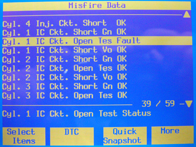
This was determined by removing the chassis ground, low reference and bolt eyelet ground each one at a time. The coil operated flawlessly with no codes using only low reference or chassis ground. The Pontiac Solstice I tested was able to function with both chassis ground and low reference wires pulled out of the coil connector, using only the bolt eyelet chassis ground.
These findings illustrate that although all coil on plug systems have the same job task no matter how many wires, they each have their own quirks. They can be monitored for trouble codes using at least three different strategies and, in some cases, are not monitored.
DVOMs and scan tools are of assistance only with some coils. Coil primary and secondary patterns can be helpful depending on the coil type, physical access and adaptors available. Collecting a scope trace of PCM command pulses is of value on three- and four-wire coils. The test that worked on all coil versions was primary current measurement using an inductive amp clamp and scope.
This measurement provides verification of both pulse command and solid electrical connections. It also provides valuable comparisons between cylinders. The next time one of these normally reliable systems fails in its task, hopefully you’ll be ready to succeed in yours.
– By Matt Dixon, Assistant Professor, SIU Carbondale