There are very few all-mechanical controls left on late-model vehicles. Almost all powertrain controls are electromechanical, using a computer as the controller.
These include powertrain control of the accelerator pedal with the latest being all-wheel drive (AWD). The brakes and damping also are electromechanical under electronic control. There are peripheral systems that are all computer-controlled, such as electronic stability control (ESC) and adaptive cruise control (ACC).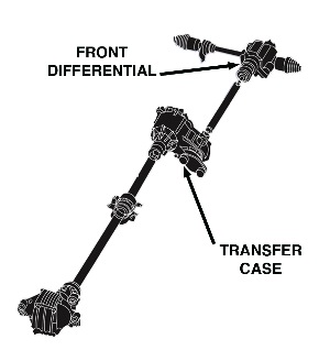
These electronic software programs are part of a controller or controllers. AWD includes three types of drive systems: four-wheel drive (4WD), AWD and on-demand AWD.
A technician at an independent tire dealership has to be more proficient in diagnosing system failures. He or she has to be familiar with more than one manufacturer and be able to understand each method of diagnosis compared to a dealership technician, who may be dealing with only one manufacturer.
The scan tool and service information are the primary tools, but a thorough knowledge of fundamental mechanical and electronic component operation also is an important tool in achieving the right fix the first time. This is a good reason to charge for diagnosing the vehicle’s systems.
A scan tool that has the capability of operating a component can be a necessity in diagnosing an operating error. Using the scan tool to activate a component can eliminate a controller-to-component communication problem. If the component does not activate, the ground should be tested before replacing the component.
Light Truck 4WD
This system has been in use since the 1940s. It is made up of a transfer case, front differential and axle assembly. Most late-model vehicles use a front differential that is mechanically engaged by a switching mechanism that uses a solenoid or motor to engage the differential; some systems have input to a controller.
All-Wheel Drive
AWD normally is associated with rear-wheel drive passenger cars and SUVs. This system uses a transfer case, front differential and a power divider that usually delivers 60% to the rear wheels and 40% to the front and is operational at all times. This type of system is used by Cadillac CTS and SRX as AWD, while Mercedes uses 4matic and Subaru uses Symmetrical AWD, to name a few.
On-Demand All-Wheel Drive
On-demand AWD is normally associated with a basic front-wheel drive vehicle and is made up of a power takeoff unit (PTU), drive shaft and rear differential.
Power Takeoff, Rear Differential
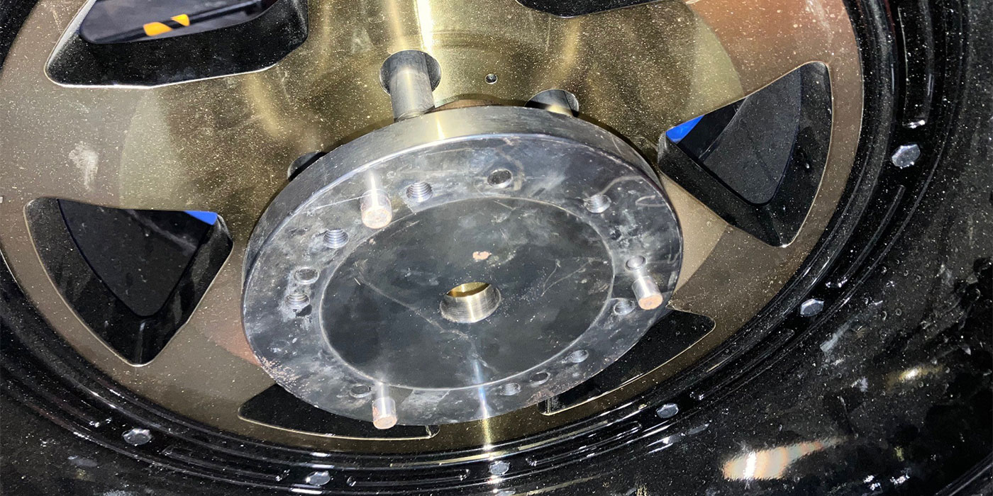
The PTU contains a ring and pinion gear attached to the output shaft of a transverse engine and transmission. The ring gear drives the pinion that is connected to the driveshaft and rear differential. The rear differential is actuated by a multi-disc wet clutch that can be engaged by an electromagnet or hydraulic pressure. The clutch attached to the rear differential unit of a Ford Edge or Chevrolet Traverse is engaged by a stationary electromagnet in the same manner as the clutch on an air conditioning compressor. 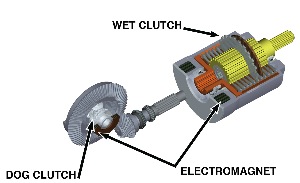
The Haldex system on the 2010 Cadillac SRX uses a hydraulic piston to actuate the wet clutch. A roller vane pump and check valve is used to charge an accumulator that supplies hydraulic pressure to a solenoid valve that meters pressure to the apply piston. Both the magnet and apply piston are actuated by electronic control using controller area network (CAN) bus input to a controller that will send a command to the differential actuator.
The actuator can communicate the state of operation of drive back to the controller; this input is shared on the CAN bus. Actuation of the drive is a result of software programming that utilizes input from the ABS wheel speed, yaw and lateral acceleration sensors. The rear differential electromechanical control input signal can be sent to the powertrain or chassis controller.
Locking Differential Systems
In the pre-computer electromechanical age, differentials used a spring-loaded clutch to limit the differential as used in the Positraction limited slip differential and the Detroit Locker that uses a dog clutch as a differential. Current differentials can be locked using an electromagnet or motor to engage a dog clutch or apply pressure to a clutch pack.
System Synergies
Controller operation uses sensor input, component feedback and output to components for the synergistic operation of the vehicle.
Diagnostics should begin with a controller status that enables the technician to monitor the status and communications between controllers on the CAN bus. This makes it a necessity to have a scan tool that can communicate with the controllers. This should be the starting point for scan tool diagnostics. The interaction of powertrain, brake, chassis and body controllers and systems will require functions to include output control that will actuate a given component to diagnose for component failures. The use of diagnostic trouble codes and data parameters is not enough to solve a difficult component or system failure.
In an electronic system, three key factors make the sensor system operational: power, ground and signal. If there is a high-resistance ground, the system may produce all kinds of problems that may not produce a trouble code.
Let’s begin with sensors. There are two types of sensors most common to this system: Two-wire and three-wire. Most three-wire sensors are digital sensors producing a square wave signal. The scan tool can be used to check reference voltage for the sensor and should range between 4.9 to 5.1 volts.
A proper ground at the three-wire sensor should be under .050 volts. Shorting the 5-volt reference to the signal wire should produce the reference voltage at the scan tool.
This checks the voltage supply circuit and the PCM ability to read the signal. Shorting the signal to ground checks the ground circuit, and the scan tool will display zero volts. Two-wire sensors used for speed sensors are a magnetic flux inductive type and produce an analog signal.
The easiest way to test these sensors is to use scan tool wheel-speed data and compare sensors. The sensor can be tested with an ohmmeter. If the sensor coil resistance is within specifications, the most probable cause of a failure is the connector. Yaw and lateral acceleration are two of the sensors that send a variety of signals to a controller.
These sensors must have a functioning power and ground to ensure the proper operation of the sensor. Once again, scan tool data and specifications are your best sources for diagnosing a sensor problem. It requires sensor input to the controller for the software to activate a component.
This gets us back to the wiring and connections in the system. Wiring and connectors can be difficult to diagnose. Having the proper tools to disassemble connectors and repair them can be an alternative to replacing a harness.