Just like your cable TV, as a signal is sent down the wire from one communication device, there needs to be another at the other end that can "unscramble" that information and turn it into readable information. These "lines" are generally referred to as BUS lines, or Data lines.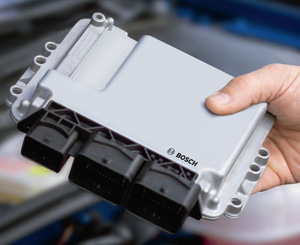
Most of the time they are pairs of two wires that are twisted together (less radio frequency (RF) interference). Some manufacturers use a two-speed CAN. One line is for low priority information, such as radio, windows, etc. A second, faster speed line is for things like transmission, theft, etc. Both systems move along the same wires at the same time.
Each of the “modules” that are on the BUS line use the information that they are programmed to read; any other information on the BUS is ignored and not read by that particular module.
What to Expect
These CAN systems are not going to go away. They’re with us for now and most likely will be even more complicated in the future.
Scanning is the key to working with these systems. A proper scanner, and not just a “code reader,” is the necessary tool to see these “TV” channels on your little screen (your scanner). A dealer-equivalent scanner is the best way to “look” at these systems. Mode $06 is another option, but one thing you don’t want to do any more is stab a wire with a test light looking for current or ground…it’s not there.
Imagine stabbing your test light into your cable TV line What do you think you would find there? You wouldn’t find anything that a test light would help with. Also, I don’t advise sending voltage or a solid ground down a data line. Would you try that with that coaxial cable coming into your house? I think not!
My advice when it comes to diagnosing power windows, gauges, or for that matter just about anything these days, is to get your scanner out and look for codes, look for a class 2 serial data line on your GM, read the mode $06 information, or whatever that particular manufacturer is calling its CAN line information.
These data information screens will give you clues as to what to look for. The next step is to go to your PC and look up the wiring diagrams. Codes are only a starting point. Remember, you still have to diagnose the cause of that code and what it means.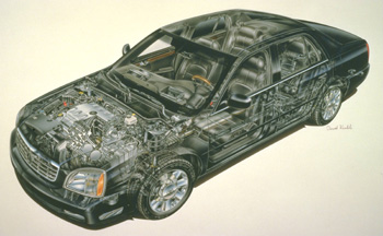
Example: 2003 Cadillac DTS
The problem with this car was with the window circuits. If the driver’s side window switch was pushed, the driver’s window and the passenger front window would go down simultaneously and would go up the same way. If you tried the front passenger window switch, nothing happened at all. Using the driver’s side rear window switch from the driver’s door switch would operate both the rear windows up and down together exactly like the front set. The car was clean, well kept and had no signs of any recent damage. As far as the owner knew, there was nothing out of the ordinary that might be a hint to possibly explain this strange window fiasco.
Scanning the car led to several history codes that could be related and some codes that couldn’t be related to the problem, that is until I went to the Class 2 serial data line information. It listed where the trouble was at…corrupted information and loss of communication on the BUS. Looking at the four door modules showed that the scanner couldn’t communicate with either of the passenger side modules. Using the scanner to operate the windows without having to move the switches showed no difference between the scanner and the actual window switch operation from the driver’s door.
Pulling the wiring diagram, it showed that the serial data lines ran from door to door and back to the BCM. There were no obvious wiring issues to be concerned with, but I did notice several slight whitish droplets dried onto the inside of the door. It looked to me like “Bondo” or sanding dust mixed with water. But, the owner knew nothing of anybody work ever done to the car. Opening the FPDM and examining the circuit board showed no water damage. With the data lines showing no communication with the modules and the wiring looking perfect, the next best thing was to change the FPDM and RRDM (Front Passenger Door Module, Right Rear Door Module).
It worked like a charm. After replacing the modules, I went back into the scanner to see if the communication had been restored. Sure enough it was, another job out the door.
I never picked up a test light like I would have on an older car and I didn’t have to pull out the old trusty tap hammer and start banging around till something moved. Using the scanner and the CAN lines showed where to go to make the repair.
History Lesson
In 1983, Bosch Corp. introduced the CAN system to the world as preparation to what they saw as an increase in the automotive electrical system advancements. In 1987, the first CAN system was officially called “CAN,” but it wasn’t until in a 1992 Mercedes Benz that a CAN system was accepted as the true first CAN system. Early GMs had a system that could have been called CAN back in 1987, but the only references were to call the lines “data lines.” It still worked about the same way but wasn’t diagnosed the same way as we do today.
In 1995, GM introduced Class 2 serial data lines, which run at a speed of 10.4 kbps. In 2004, GM went to its next generation system called GMLAN (local area network), which had a two-speed system: low (33.3 Kbps) and high (500 Kbps). Mercedes Benz uses several BUS lines; on one car I counted 5 different CAN speeds.
With the speed and flexibility of these electronic systems manufacturers can create in today’s cars, I can only imagine how far all this information is going to go. At some point in time, that wiring will be a thing of the past, too. Everything in the car could someday go completely wireless; modules will get smaller, faster and less likely to fail. Scanning could be done without even seeing the car in a repair shop. Just dial your cell phone to your shop of choice and a complete diagnostics could be done right then. I know it sounds a little “out there,” but just imagine what a mechanic from the ’50s would think of today’s cars.