 There is no way to quickly tell if a Wheel Speed Sensor (WSS) is passive or active. Both sensors have two wires and are located in the same position on the vehicle. Often, the service information will not indicate what types of sensors are on the vehicle. Trouble codes will not indicate if the sensors are passive or active.
Passive Wheel Speed Sensors
Passive wheel speed sensors are often referred to as “old school” or as conventional wheel speed sensors. These are the older version of wheel speed sensors that must be understood before moving onto newer active sensors.
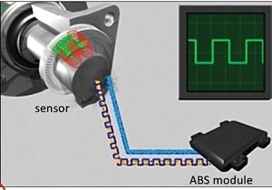
Passive WSS are two wire permanent magnet sensors. The sensors output an Alternative Current (AC) voltage that is generated when a toothed tone ring or reluctor passes by the sensor. The ABS module monitors the change in frequency and amplitude as the wheel rotates. A sensor might not display 0 mph, but 3-5 mph; this is normal. But, if there is an unwanted activation at low speeds, using a scan tool may not be the best method. Do not get hung up on these low speeds; further tests are needed. 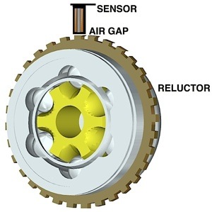
Graphing the WSSs can be done with a scan tool. You should look for a clean signal from each sensor. All signals should track the same. When the vehicle is stopped, they should all evenly drop.
When testing a passive WSS, the positive lead of the meter should be connected to the signal wire. The negative should go to the ground or a chassis ground depending on the test you are doing.
The sensor and/or harness should be disconnected from the circuit so you are not measuring resistance in the ABS unit. The typical reading for a passive wheel speed sensor is between 1,000 and 2,500 ohms. This is a normal range for all passive sensors. The specification for active sensors is between 1,000 and 2,500 ohms.
AC Voltage
With the meter set to AC voltage, spin the wheel by hand. The sensor should produce between .5 to 1 volt of AC current. The faster the wheel is spun, the more voltage is produced.
Bias Voltage Passive Sensors
Some vehicles will send a DC voltage to the sensor through the ground wire. The signal will ride up on the DC signal. This is done so that the sensor can be tested by the ABS system without the vehicle moving. These types of vehicles will set WSS codes the moment the key is turned on. You can clear a WSS code and the moment the key is turned on, the code will immediately be back.
The ABS computer is looking at the voltage coming back from the sensor. High resistance or an open circuit can be immediately detected. Often, with these systems the trouble is not the sensor, but the bias voltage as it goes through the harness and connectors.
If the signal is viewed on a scope, the voltage will raise above the ground or zero line. On this vehicle, there is a 2.5-volt bias. To measure this, have the ground lead on the battery ground, and the positive lead connected to the signal wire. Without the wheel spinning, you can observe the DC voltage being supplied to the circuit. 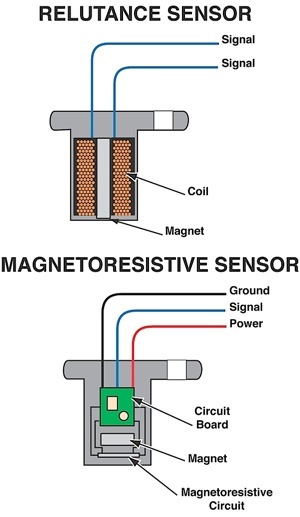
With the sensor disconnected, connect the positive lead to the signal wire and the negative lead to the other side that is the ground for the ABS module. This voltage comes directly from the ABS module and will be between 1.5 and 5 volts. This is the bias voltage from the ABS module. Any voltage outside of the manufacturer’s specification may indicate a problem with the harness.
Unwanted ABS Activations in Passive WSS
You never want to underestimate a little bit of rust under a WSS. A little bit of rust between the WSS and the knuckle or hub can disturb the air gap between the WSS and the tone ring.
You want to clear the rust and polish the surface. Never grind the surface. This could cause further problems. If removing the corrosion does not resolve the problem, you should look at the tone wheel. Tone rings or wheels are mounted on axles, CV joints and hubs. The majority of tone wheels are pressed on to these components.
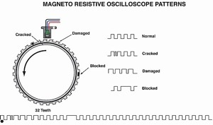
Corrosion can get in between the components and damage the tone ring. The teeth of the tone ring pulse the sensor and generate AC voltage in the sensor. If a tooth is missing or out of alignment, it can cause unwanted ABS activation.
Other electrical outputs can cause interference in the WSS wires. Wires for the ignition system, charging and serial data buses can cause interference that can lead to false activation. Some OEMs have even issued TSBs directing technicians to reroute or even shield affected wires.
Active Wheel Speed Sensors
Active WSS use two wires and look like passive wheel speed sensors. Active WSS are used on most newer vehicles because they are more accurate at lower speeds and can detect 0 mph. Also, active sensors can even detect if the vehicle is moving in reverse.
Active WSSs output a digital signal. The signal is a Direct Current (DC) square wave signal. The signals are different than a camshaft or crankshaft position sensor.
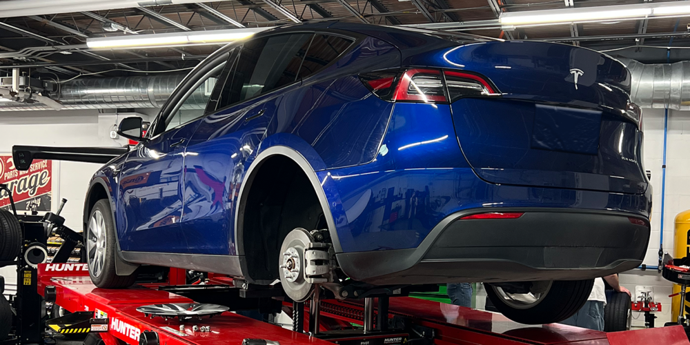
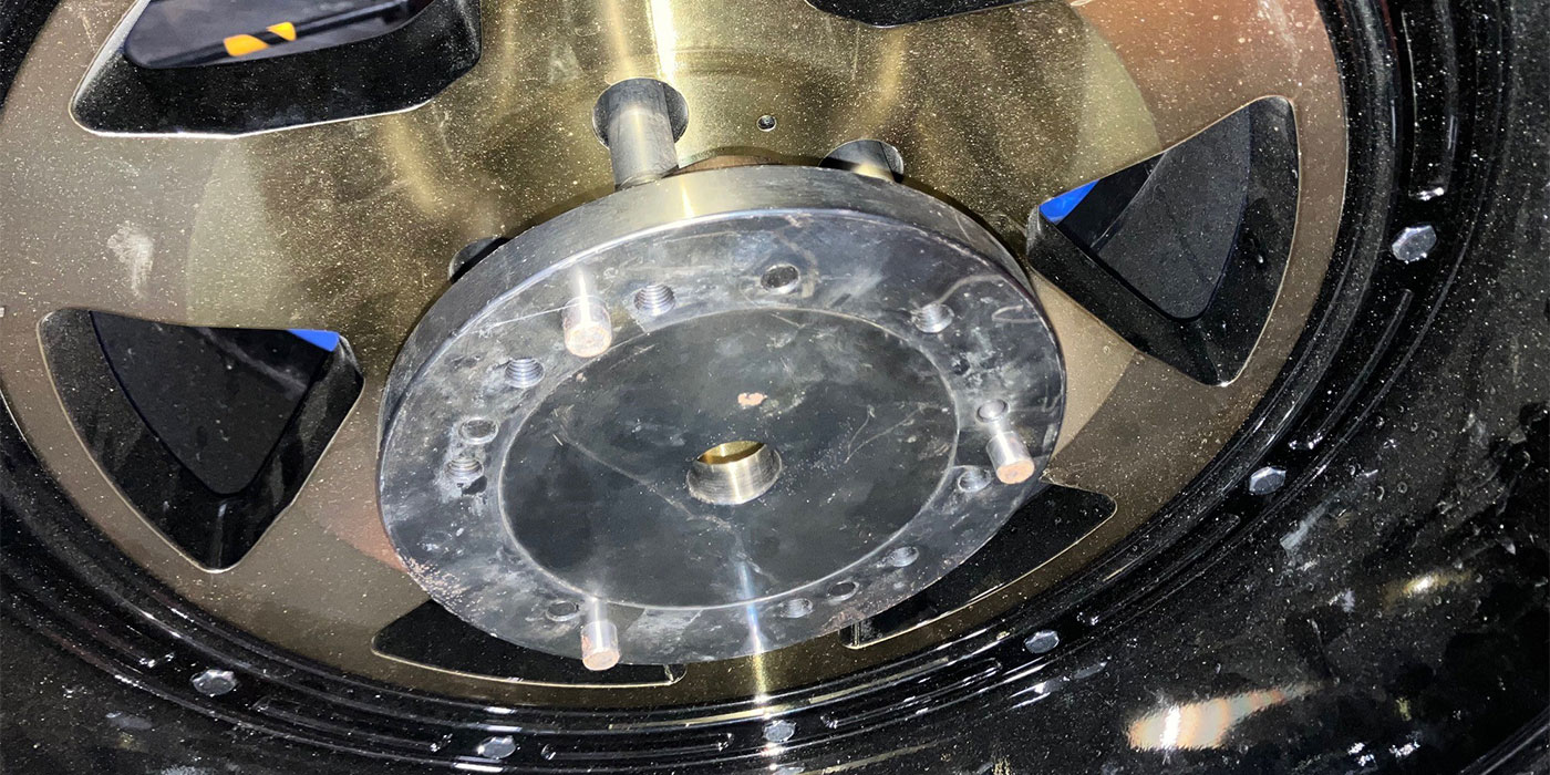
The tone wheel on most active sensors is mounted in the grease seal for the bearing or inside the unitized hub unit. The tone wheel for an active sensor has magnetic teeth that have alternating north and south poles. You cannot see the teeth on these rings. The only way to detect on some bearings is to pass a small ferrous (magnetically attracted) metal component by the rings. Some bearing manufacturers offer a special tool, but a paperclip should work in a pinch.
The end of an active WSS is typically a flat blade tip that is mounted next to a tone ring. The sensor’s tip is typically buried inside a hub or knuckle.
Testing
Like passive WSSs, it is possible to look at the data from the WSS using a scan tool. A scan tool can be used ri graph the WSSs. You should look for a clean signal from each sensor. All signals should track the same. When the vehicle is stopped, they should all evenly drop.
Active wheel speed sensors have two wires. One wire provides 12 volts to power the sensor. The other wire is the signal wire. The signal wire changes the frequency of the waves as the magnets of the tone ring pass by. This makes for a very accurate sensor at low speeds.
Telling the Difference
If you disconnect the sensor and probe the harness with the ground lead connected to the battery ground and the positive lead into the harness, you will see a voltage of 11.30 with the engine off.
If you probe the signal wire, you will see a voltage of .03volts. You might confuse this reading with a bias voltage passive sensor, but the values are significantly different.
When the vehicle is started, the power supply changes from 11.30 volts to 13.69 volts, which is the charging system voltage. But, the signal wire remains at .03 volts. When the sensor is plugged into the harness, the voltage drops to 12.07 volts with current running through the sensor. This voltage does not change if the vehicle is moving; it is just a power supply.
With the black lead on the battery ground and the red lead back probed into the signal line, the wave pattern generated by the sensor can be observed.
What is unusual is the voltage levels of the square wave pattern. The wave goes from between .6 to 1.2 volts. The square wave is only .6 volts high and never connects to ground or zero. Also, it never shows the battery voltage. This is a very small square wave out of an active sensor.
If you were to back probe the connected sensor with the positive lead connected to the signal wire and the negative lead to the other wire connected to the sensor’s power supply, you would still see a square waveform. This waveform would toggle between 12 and 12.7 volts. This is still a .6-volt square wave like is seen above.
Resistance Testing
Active WSS cannot be tested by using the resistance across the sensor. If you do measure an active sensor with a meter, it will produce a reading around 3.5 millions ohms. If the leads are reversed, you will get an infinite reading indicating an open circuit. The second reading would indicate a dead passive WSS or a normal active WSS. This makes the results dubious.
On the harness side, it is possible to determine if the sensor is passive, passive with a bias voltage or active. Passive systems have no voltage. Bias voltage systems have between 1.5 to 5 volts. Active systems have between 12 and 12.7 volts.
Amp Meter Testing
An amp meter can be used to check active wheel speed circuits. The amp meter must be installed in series in the signal line. Setting this up in reality can be tricky with jumper wires. And the voltage test above might be quicker. The amp meter should read between 7 and 14 milliamps.
Curveball: Honda, Acura and BMW
On some newer vehicles, when the sensor is unplugged, the power or bias is turned off. If the sensor was plugged in and the key was cycled, it would appear again. In these cases, back probing the sensor would be the best way to test the sensor.