 The ASE A5 Test has a large section (about 43%) dedicated to hydraulic, power assist and parking brake system diagnosis and repair. As it specifically pertains to power assist, you must know how to:
- Check vacuum supply (manifold or auxiliary pump) to vacuum-type power booster.
- Diagnose vacuum-type power booster units for vacuum leaks and proper operation; inspect the check valve for proper operation; repair, adjust or replace parts as necessary.
- Diagnose hydroboost systems for leaks and proper operation; repair or replace parts as necessary; refill and bleed system following manufacturers’ specifications.
Vacuum Power Assist Service
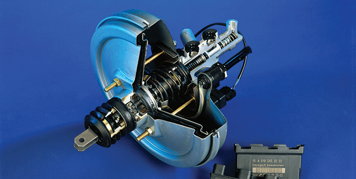
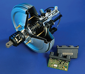
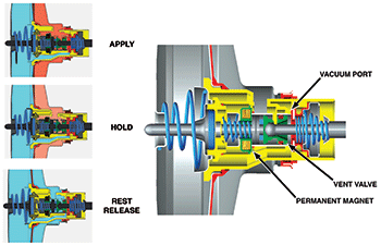
Most late-model vehicles use a vacuum booster to help apply the brakes, usually located behind the master cylinder on the firewall. Vacuum brake boosters have four modes of operation: rest, apply, hold (or balance) and release.
In apply mode, the pressure from the brake pedal causes the push rod to move the treadle valve forward and close the vacuum port to the vacuum diaphragm chambers and isolate the vent valve. As the push rod continues forward, it opens the vent valve to atmospheric pressure, which pressurizes the boost chamber(s) to create a force on the diaphragm(s), power piston and the push rod connected to the master cylinder pistons.
In hold or balance mode, the pressure generated by the brake pedal push rod equalizes with the pressure from the master cylinder piston push rod. This causes the treadle valve to close the vent valve.
Release and rest mode are the same. When the pressure generated by the pedal is released, the vacuum valve opens, the pressure from the boost chamber(s) is evacuated, and the power piston is returned to its rest position by the spring in the main vacuum chamber. The vacuum check valve is a key component to the operation of the booster.
A manifold vacuum of 20” Hg or greater can be achieved during engine deceleration. The booster chambers can be evacuated and retained at this pressure by a properly operating check valve. A leak in the valve can cause a reduction in the performance of the booster and increase pedal travel.
Vacuum Boosters Require Three Basic Tests:
- Operational test
- Vacuum supply test
- Inlet check valve test
Booster Operational Test
Check pedal feel and vacuum booster function while test-driving the vehicle. With the engine off, apply the brake pedal repeatedly with medium pressure until the booster reserve is depleted. At least two brake applications should have a power-assisted feel before the pedal hardens noticeably. A pedal that feels hard immediately, or after only one brake application, may have a vacuum leak or a low level of engine vacuum.
Inspect the vacuum supply hose to the booster for kinks, cracks or other damage. Check engine vacuum at idle with a vacuum gauge.
To test booster function once the reserve is depleted, hold moderate pressure on the brake pedal and start the engine. If the booster is working properly, the pedal will drop slightly.
Booster Vacuum Supply Test
 With the ignition off, pump the brake pedal to deplete the booster reserve. Disconnect the vacuum supply hose from the booster and connect a vacuum gauge to the hose using a cone-shaped adapter to check for source vacuum.
Start the engine and allow it to idle while observing the vacuum gauge. Although the amount of vacuum will vary by application, most will register between 15” and 20” Hg (50 and 70 kpa) at idle.
If the reading is low, check to see if the vacuum hose is kinked, clogged or cracked. If the hose is not at fault, suspect an engine mechanical problem such as leaky valves, worn rings, an intake manifold vacuum leak, improper cam timing, etc.
Vacuum Inlet Check Valve Test
To test the vacuum check valve, disconnect the vacuum supply hose from the intake manifold or vacuum pump and blow into the hose. If air passes through the valve into the booster, the check to see if the valve is defective and should be replaced.
Hydroboost Power Assist Service
 The hydroboost power assist system performs the same function as the vacuum assist system, with the difference being the use of hydraulic pressure instead of vacuum to provide power assist for the brake system. Hydraulic pressure provides a greater amount of assist than vacuum assist systems.
Hydroboost uses pressure from the power steering pump to provide braking boost, and includes a high-pressure accumulator that has enough capacity to provide several power-assisted stops in the event that the power steering pump belt breaks or a hose ruptures.
A hydroboost system inspection must include a check of the power steering hoses and pump for leaks, the power steering fluid level and the drive belt tension. Hydroboost operation and accumulator performance must also be tested.
The control of fluid flowing in and out of the hydroboost is provided by spool valves. Spool valves are used in a variety of hydraulic components, such as the valve body of an automatic transmission, and are basically hollow cylinders with a number of rings machined into them. The surface of a spool valve is highly polished to form a sealing surface. The raised portions of the cylinder are called lands while the indentations are called annular grooves.
Hydroboost Function Test
With the engine off, apply the brake pedal five or more times with medium force to discharge the accumulator. The pedal feel will harden noticeably. Next, apply the brake pedal with medium force, and then start the engine. If the booster is working properly, the pedal will drop toward the floor, and then push back upward slightly. If the booster passes this test, move on to the accumulator test.
However, if there is no change in the pedal position or feel, the booster is not working. Check the power steering system to determine whether the problem is in the pump or the booster.
Hydroboost Accumulator
The hydroboost system uses a high-pressure accumulator to store power steering fluid under pressure in the event of a failure. The accumulator could be either spring-loaded or nitrogen gas.
In the event of a loss of pressurized fluid, the accumulator will provide two to three power-assisted stops. Upon the first braking application after an engine stall or loss of power steering, approximately 60% to 75% of the normal assist would be available. Releasing and applying the brakes again would leave approximately 30% to 40% assist, then about 10% to 20%, until all of the stored reserve assist is depleted.
During normal operation, the accumulator is charged by pump pressure though a check valve assembly. The check valve allows fluid into the accumulator and prevents it from escaping. When the pressure in the power chamber is lost due to a failure, the input rod linkage will override the power piston linkage and cause the check valve to open. The open check valve will release the stored fluid in the accumulator into the power chamber, which will provide the power assist.
Hydroboost Accumulator Test
To test the ability of the system to store a short-term high-pressure charge in the accumulator, start the engine and allow it to idle. Charge the accumulator by turning the steering wheel slowly one time from lock to lock; do not hold the steering at full lock for more than five seconds. Switch the engine off, release the steering wheel, and repeatedly apply the brake pedal with medium force. If the accumulator can hold a charge, the hydroboost unit will provide several applications — hydroboost I units will provide two or three and hydroboost II units will provides one or two.
As the accumulator charges on a hydroboost I system, a slight hissing sound should be audible as fluid rushes through the accumulator-charging orifice. Once the accumulator is charged, switch the engine off and do not apply the brake pedal for one hour. At the end of the hour, repeatedly apply the brake pedal with medium force. Once again, a hydroboost I unit should provide two or three power-assisted applications, and a hydroboost II unit should provide one or two.
If the hydroboost unit fails these tests, usually there is a leak — either the accumulator of a hydroboost I unit, or the accumulator/power-piston assembly of a hydroboost II unit. In either case, the booster must be rebuilt or replaced. However, if a hydroboost I system fails the test but doesn’t make the hissing sound that indicates charging, the fluid in the system is probably contaminated.
Never begin any work on a hydroboost system until the dangerously high pressure stored in the accumulator is discharged by pumping the brake pedal numerous times with the engine off.